Pilot flame characteristics, Cleaning and servicing – Empire Comfort Systems VFSUR18-2 User Manual
Page 17
24552-0-0608
Page 17
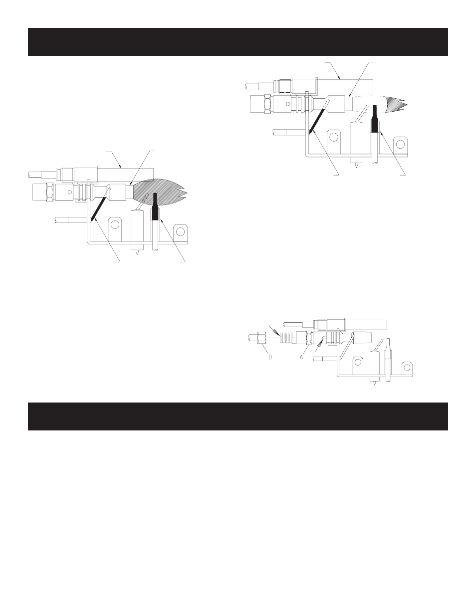
Figure 13 shows a correct pilot flame pattern. The correct flame
will be blue and will extend beyond the thermocouple. The flame
will surround the thermocouple just below the tip. A slight yellow
flame may occur where the pilot flame and main burner flame meet.
Figure 14 shows an incorrect pilot flame pattern. The incorrect
pilot flame is not touching the thermocouple. This will cause the
thermocouple to cool. When the thermocouple cools, the heater
will shut down.
VFSUR PILOT
Correct Pilot Flame Pattern
Figure 13
Incorrect Pilot Flame Pattern
Figure 14
If pilot flame pattern is incorrect, as shown in Figure 14
• See Troubleshooting, page 19.
Cleaning and Maintenance/Pilot
Oxygen Depletion Sensor Pilot (Figure 15)
When the pilot has a large yellow tip flame, clean the Oxygen
Depletion Sensor as follows:
1. Clean the ODS pilot by loosening nut B from the pilot tubing.
When this procedure is required, grasp nut A with an open end
wrench.
2. Blow air pressure through the holes indicated by the arrows.
This will blow out foreign materials such as dust, lint and
spider webs. Tighten nut B also by grasping nut A.
Figure 15
PILOT FLAME CHARACTERISTICS
THERMOPILE
PILOT
THERMOCOUPLE
(LPG)
THERMOCOUPLE
(NATURAL)
THERMOPILE
PILOT
THERMOCOUPLE
(LPG)
THERMOCOUPLE
(NATURAL)
Annual inspection and cleaning by your dealer or qualified
service technician is recommended to prevent malfunction
and/or sooting.
TURN OFF HEATER AND ALLOW TO COOL BEFORE
CLEANING.
Remove logs, handling carefully by holding gently at each end.
Gloves are recommended to prevent skin irritation from ceramic
fibers. If skin becomes irritated, wash gently with soap and water.
Refer to manual for correct log placement.
PERIODIC CLEANING – Refer to parts diagram for location
of items discussed below.
• Do not use cleaning fluid to clean logs or any part of heater.
• Logs - brush with soft bristle brush or vacuum with brush
attachment.
• Remove loose particles and dust from the burner areas,
controls, piezo covers and grate. Don’t remove media from
inside burner box.
• Inspect and clean burner air intake hole. Remove lint or
particles with brush. Failure to keep air intake hole clean will
result in sooting and poor combustion.
ANNUAL CLEANING/INSPECTION – Refer to parts diagram
for location of items discussed below.
• Inspect and clean burner air intake hole. Remove lint or
particles with vacuum or brush. Failure to keep air intake hole
clean will result in sooting and poor combustion.
• Inspect and clean all burner ports.
• Inspect ODS pilot for operation and accumulation of lint at air
intake holes.
• Verify flame pattern and log placement for proper operation.
• Verify smooth and responsive ignition of main burner.
• Check level of ceramic media in burner. Burner should be full,
up to the level of openings in burner top.
CLEANING AND SERVICING