Welding principles 6. ratings plate 7. maintenance – Sealey SUPERMIG130 User Manual
Page 4
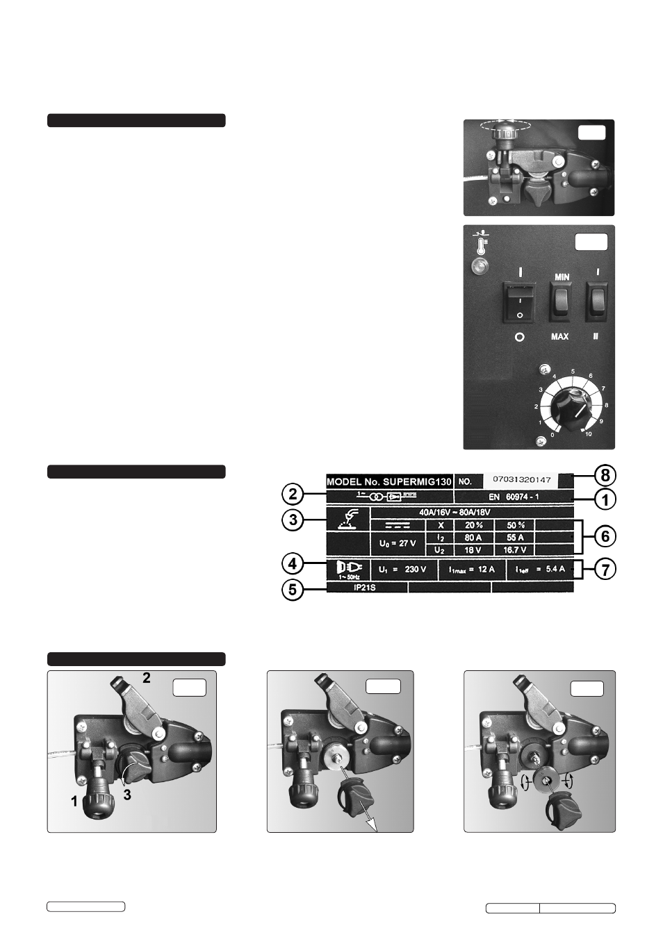
On the front of the welder is the ratings plate, giving the
following data:
1 - The standard relating to the safety and construction
of arc welding and associated equipment.
2 - Inverter-transformer-rectifier.
3 - Welding with a continuous flow of welding wire.
4 - Single-phase AC supply.
5 - Rating of internal protection provided by casing.
6 - Output
U0: Maximum open-circuit voltage.
I2, U2: Current and corresponding voltage.
X: Welding ratio based on a 10 minute cycle. 20% indicates
2 minutes welding and 8 minutes rest, 100% indicates
continuous welding.
A/V-A/V: Welding current adjustment range and corresponding voltages.
7 - Mains Supply U1: Rated supply voltage and frequency. Imax: Maximum current.
I1eff: Maximum effective current.
8 - Serial Number. Specifically identifies each welder.
5.1.
Mig/Mag welding
Welding wire is automatically fed through an insulated liner to the tip of the torch. The torch consists of a
switch, liner, gas hose, and control cable. The switch activates the wire feed roller and the gas flow.
Releasing the switch stops wire feed and gas flow. The weld current is transferred to the electrode (the
wire) from the contact tip at the torch end. Four settings control the current to the electrode. Settings are
Min/1 = low, then Min/2, Max/1 and Max/2 = high. Wire speed must be adjusted according to current
output. The higher the current the faster the wire speed. A gas cup fits over the contact tip to direct gas
flow towards the weld, ensuring that the arc welding process is shielded from oxidisation. The shielding gas
also assists heating of the weld. The torch is connected to the positive side of a DC rectifier, and the
negative clamp is attached to the workpiece.
5.2.
Preparation for welding
IMPORTANT! BEFORE YOU COMMENCE, MAKE SURE THE MACHINE IS SWITCHED OFF AT THE
MAINS. IF WELDING A CAR, DISCONNECT THE BATTERY OR FIT AN ELECTRONIC CIRCUIT
PROTECTOR. ENSURE THAT YOU READ, UNDERSTAND AND APPLY THE SAFETY INSTRUCTIONS
IN SECTION 1.
5.2.1.
To ensure a complete circuit, the negative lead must be securely attached to the workpiece, close to the
weld area. Best connection is obtained by grinding the point of contact on the workpiece before connecting
the clamp.
5.2.2.
The weld area must be free of paint, rust, grease, etc.
5.3.
Gas types and their use
Welding mild steel with CO² gas is appropriate for most welding tasks where spatter and high build-up of
weld do not pose a problem.
To achieve a spatter free and flat weld however, requires an Argon/CO² mixture.
5.3.1.
To weld aluminium use: Argon Gas 0.8mm Contact Tip 0.8mm Aluminium Wire (MIG/2/KAL08).
5.3.2.
The following table is an estimated duration of cylinders based on a flow rate of 2 litres per minute. Actual
duration will be dependant upon various job conditions including the operator’s welding technique. All
times are therefore approximate.
Disposable cylinders: (CO²) CO²/100 390g = 1-1/4hours. (CO² ) CO²/101 600g = 2 hours.
(Argon) MIG/ARG/100 300g = 1hour. (CO²/Argon Mix) MIG/MIX/100 300g = 1 hour.
Note: When comparing prices, always check fill weights.
5.4.
Thermal Protection
Should the welder become overheated due to prolonged use beyond the stated duty cycle the thermal
protection will cause the welder to cut out and the orange light on the front panel will illuminate. Wait for
fifteen minutes for the welder to cool down at which time it will reconnect automatically.
WARNING! Do not turn gas cup anticlockwise, as this will damage the internal spring.
4.3.7. Cut wire so that it is protruding approximately ¼" from the tip.
4.4. Setting wire tension
IMPORTANT: Too little or too much tension will cause erratic wire feed and result in poor welding.
4.4.1. Tension between rollers is checked by slowing down the wire between your fingers. If top feed roller skids the tension is correct. Use as low a tension as
possible, too high a tension will deform the wire and result in a blown fuse.
fig.11
fig.10
fig.9
fig.7
fig.8
DANGER! Unplug the welder from the mains power supply before performing maintenance or service.
7.1.
Wire feed unit: Check the wire feed unit at regular intervals. The feed roller wire guide plays an important part in obtaining consistent results. Poor wire
feed affects welding. Clean the rollers weekly, especially the feed roller groove, removing all dust deposits.
7.2.
Torch: Protect the torch cable assembly from mechanical wear. Clean the liner from the machine forwards by using compressed air. If the liner is blocked
it must be replaced.
5. WELDING PRINCIPLES
6. RATINGS PLATE
7. MAINTENANCE
SUPERMIG130 Issue No:2(L) 26/08/14
Original Language Version
© Jack Sealey Limited