Sealey GSS150819SD User Manual
Page 10
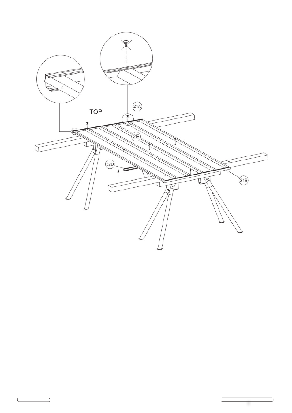
7.2.1 Place panel 2E on your work table.
7.2.2 Fit top and bottom channels 21A and 21B to panel by firstly sliding and finally tapping into place as indicated
by arrows in the diagrams. Note that the smaller flange on the channels should always be adjacent to the out
side face of the panel. The outside face is the top face in both diagrams.
7.2.3 Fit item 32D the mid height wall channel to the panel and position it by the pre-punched holes and 10mm
long self tapping screws. Note this channel is fitted with the flat face uppermost, ie. nearest the “top”.
7.2.4 With self tapping screws fix item 21B to bottom edge, but do not screw fix item 21A to top edge at this
stage,see places marked with asterisk *.
7.2
ASSEMbLE THE END WALL PANEL (oppposite door).
© Jack Sealey Limited
GSS150819SD Issue: 1 - 20/08/12
Original Language Version
*
*
*