Fig.12, Fig.9 fig.8, Fig.10 fig.11 – Sealey PWDM3600 User Manual
Page 5: Maintenance (engine)
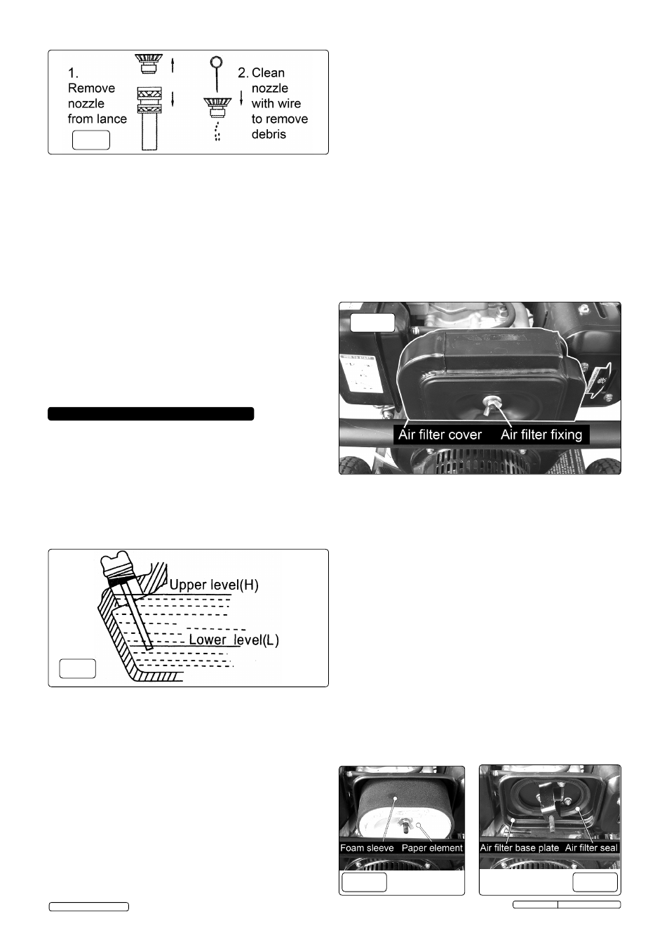
fig.12
7.4. FUEL FILTER. The fuel filter is in the neck of the fuel tank.
7.4.1 Clean it every 100 hours and replace it every 500 hours.
7.5. ENGINE STORAGE. If the unit is not to be used for more than
one month the following procedure should be followed:
7.5.1 Change the oil. Operate the engine for 3 minutes to warm the
oil then stop the engine using the shut down procedure
described in section 5.4. There is a hole in the chassis below
the oil drain plug. See fig.6. Place a suitable container below
the hole, remove the plug and allow the oil to drain. Replace
the drain plug and refill with fresh oil. Check the oil level using
the dipstick. Dispose of the old oil according to local authority
guidelines.
7.5.2 Drain the diesel fuel from the fuel tank, fuel line and fuel tap.
7.5.3 Push and hold down the decompression lever whilst the engine
is turned over 2 or 3 times using the recoil starter. Let go of the
decompression lever then pull the starter handle slowly until an
increase in pressure is felt indicating that the piston has
commenced its compression stroke and leave it in this position.
This closes both the intake and exhaust valves and prevents the
inside of the cylinder from rusting.
7.5.4 Cover the unit and store it in a clean dry place that is well
ventilated and away from open flame or sparks.
7. MAINTENANCE (ENGINE)
7.1. Change engine oil after the first 20 hours of operation.
Thereafter, change oil every three months or every 100 hours of
operation. Change oil more often if engine is operated under
heavy load, or in high ambient air temperatures. During normal
operation, partially burned fuel, small particles of metal from the
cylinder walls, pistons, bearings and combustion deposits will
gradually contaminate the oil. If the oil is not changed regularly,
these foreign particles can cause increased friction and a
grinding action which shortens the life of the engine. Fresh oil
also assists in cooling. Old oil will gradually thicken and
lose its cooling ability as well as its lubricating qualities.
6.2.
WATER INLET FILTER. Check and clean the water inlet filter
every 50 operating hours. The filter is moulded into a rubber
washer. Unscrew the brass connector from the black fitting on
the water inlet on the pump. Push the black fitting backwards
which will eject the filter/washer and then clean the filter
washer. If the filter is damaged in any way it should be
replaced.
6.3.
DETERGENT FILTER. Check and clean the detergent filter at
the end of the detergent input tube on a regular basis.
6.4.
WINTER STORAGE. Fill the pump with an antifreeze
mixture before storing in a frost free, safe, dry area for the
winter. Introduce the antifreeze by the following method:
6.4.1. Shut off the water supply and disconnect the supply hose.
Relieve pressure within the pump by squeezing the gun
trigger. Remove the high pressure hose and let all water drain
from it. Hold gun/lance with nozzle downwards and pull
trigger until all water has drained out.
6.4.2. Connect a short length of garden hose to the water inlet and
using a funnel pour an antifreeze mixture into it.
6.4.3. Pull the recoil starter several times to circulate the antifreeze
through the pump. Continue to add antifreeze and pull the
recoil until antifreeze is expelled from the pump.
fig.9
fig.8
7.2. CHECKING THE OIL LEVEL. Ensure the unit is level.
7.2.1. Unscrew the dipstick/oil filler cap (see fig.6) and wipe it clean
of oil. Note that the maximum oil level should be just below
the opening of the filler neck.
7.2.2. Check the oil level by seating the dipstick into the hole without
screwing it in. See fig.9 above. On removal the oil level should
be between the two marks on the dipstick. If it is at the lowest
level or below, top-up immediately with an SAE10W30 (CC or
DD) oil.
7.2.3. Screw dipstick fully home to seal oil fill hole. Note: The engine
is
fitted with a low oil sensor which will automatically shut the
engine down in a low oil situation. The sensor may also
operate if the unit is not on a level surface.
7.3. CHECKING THE OIL STRAINER. (see fig.6)
7.3.1. Check, clean and/or replace the oil strainer every time the oil
is changed as this can only be done when the sump is empty.
Undo the retaining bolt and withdraw the strainer. Clean/rinse
the strainer in clean diesel fuel and re-insert it. Ensure the
retaining bolt is replaced.
7.6. AIR FILTER. The air filter is situated between the engine
and the frame, below the frame handle (see fig.10). To access
the air filter element unscrew and remove the wing nut on the
front of the cover. Pull the black cover outwards and off its
threaded mounting rod until it touches the frame, then lift it
upwards and away to reveal the element as shown in fig.11.
Unscrew the wing nut from the top of the filter element and pull
the element from the threaded rod.
7.6.1. Remove the foam sleeve from the outside of the element and
tap
the element on a hard surface to dislodge any dust
accumulations
from the paper part of the element. If
compressed air is available it can be used to blow out the
element. Do not use a brush as this will be more likely to force
dirt into the paper. If the paper element is heavily contaminated
replace it.
7.6.2. Wash the foam sleeve with a household detergent or a high
flash-point solvent and squeeze dry. When the sleeve is
thoroughly dry, soak it in clean engine oil. Squeeze out any
excess oil and stretch the sleeve back over the element. Place
the element back over the threaded rod and make sure it seats
properly onto the seal on the air filter base plate as in fig.12.
Secure the element with the wing nut. Place the outer cover
back over the element and secure it with the other wing nut.
7.6.3. The whole filter should be replaced after every 500hrs of service.
fig.10
fig.11
Original Language Version
© Jack Sealey Limited
PWDM3600 Issue: 1 - 08/05/13