Introduction & specifications, Preparation, Fig.4 fig.3 fig.1 – Sealey SA2415 User Manual
Page 2: Operation, Fig.2
2. INTRODUCTION & SPECIFICATIONS
Aluminium cylinder head with cast iron cylinder gives added resistance to wear. Suitable for general-purpose workshop applications. Pump head
directly coupled to heavy-duty induction motor for reliable and quiet operation. Welded tank complies with latest European standards. Fitted with
fully automatic pressure cut-out switch with twin gauges displaying tank and working pressures. Fitted with ASTA/BS approved non-rewirable plug.
2.1.
Specifications
3
Read the instructions relating to any accessory to be used with this compressor. Ensure the safe working pressure of any air appliance
used exceeds compressors output pressure. If using spray a gun, check that the area selected for spraying is provided with a air change
system/ventilation.
3
Ensure the air supply valve is turned off before disconnecting the air supply hose.
3
To move the compressor use the handle only. Lift the compressor so that the front leg gives enough clearance for manoeuvring but
maintain unit’s centre of gravity in front of the wheels.
DO NOT attempt to lift or move the compressor by any other means.
3
Use the compressor in a well ventilated area and ensure it is placed on a firm surface.
3
Keep tools and other items away from the compressor when it is in use, and keep area clean and clear of unnecessary items.
3
Ensure the air hose is not tangled, twisted or pinched.
3
Keep children and unauthorised persons away from the working area.
7
DO NOT dis-assemble compressor for any reason. The unit must be checked by qualified personnel only.
7
DO NOT use the compressor outdoors, or in damp, or wet, locations.
7
DO NOT operate within the vicinity of flammable liquids, gases or solids.
7
DO NOT touch compressor cylinder, cylinder head or pipe from head to tank as these may be hot.
7
DO NOT attempt to move the compressor by pulling the air hose. Only move the compressor by
the handle.
7
DO NOT use this product to perform a task for which it has not been designed.
7
DO NOT deface the certification plate attached to the end of the compressor tank.
7
DO NOT cover the compressor or restrict air flow around the unit whilst operating.
q
DANGER! DO NOT direct the output jet of air towards people or animals.
7
DO NOT operate the compressor without an air filter.
7
DO NOT allow anyone to operate the compressor unless they have received full instructions.
WARNING! The air tank is a pressure vessel and the following safety measures apply:
7
DO NOT tamper with the safety valve, DO NOT modify or alter the tank in any way and DO NOT strap anything to the tank.
7
DO NOT subject the tank to impact, vibration or to heat and DO NOT allow contact with abrasives or corrosives.
3
Drain condensation from tank daily and inspect inside walls for corrosion every three months and have a detailed tank inspection carried out
annually. The tank shell must not fall below the certified thickness at any point.
WARNING! If an electrical fuse blows, ensure it is replaced with an identical fuse type and rating.
3
When not in use, store the compressor carefully in a safe, dry, childproof location.
Model
Motor
Output
(hp)
Voltage
/Phase
Current
(A)
Compressor
Displacement
cfm(ltr/min)
Max free air
delivery
cfm(ltr/min)
Tank
Capacity
(l)
Max.
Pressure
(psi/bar)
Noise
Level
(dB.A)
Noise
Power
(Lw.A)
Weight
(kg)
Dimensions
(W x D x H)
SA2415
1.5
230/1
13
6 (170)
4.2 (119)
24
116/8
70
95
21
580 x 280 x 550
SA2420
2.0
230/1
13
6.7 (190)
4.7 (133)
24
116/8
72
95
25
620 x 330 x 610
SA5020
2.0
230/1
13
7 (200)
4.8 (135)
50
116/8
71
95
30
740 x 400 x 590
SA5025
2.5
230/1
13
8.3 (235)
5.8 (165)
50
116/8
72
95
34
740 x 400 x 590
3. PREPARATION
3.1.
Remove compressor from packaging and inspect for any shortages or damage. If anything is
found to be missing or damaged contact your supplier.
3.2.
Save the packing material for future transportation of the compressor. We recommend that
you store the packing in a safe location, at least for the period of the guarantee. Then, if
necessary, it will be easier to send the compressor to the service centre.
3.3.
Attach wheels to the compressor as shown in fig.2.
3.4.
Confirm that the mains voltage corresponds with the voltage shown on the compressor data
plate.
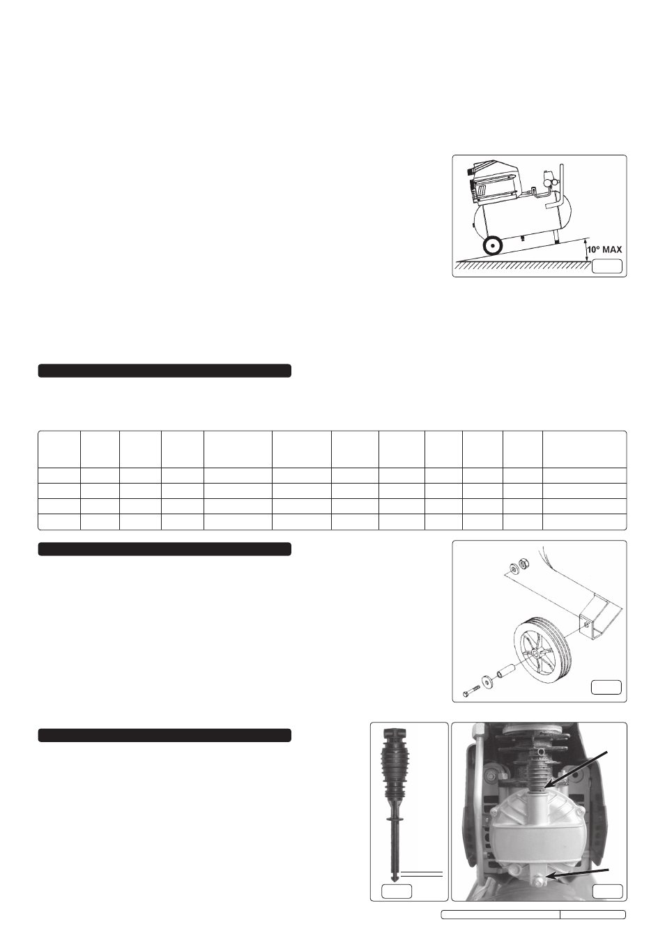
3.5.
The compressor should be operated on a flat surface, or one that does not exceed 10° either
transversely or longitudinally (fig.1) and should be in a position that allows good air circulation
around the unit.
3.6.
Remove the plastic transit plug from the oil filler hole and replace it with the dipstick/breather
as shown in figs.4 or 9 (depending on model). It is a push fit, ensure that it is pushed fully home.
3.7.
Before using the compressor check the oil level using the dipstick. If the oil is not up to
the mark as shown in fig.3 it should be topped up with Sealey CPO Compressor oil.
fig.4
fig.3
fig.1
MIN
MAX
A
B
4. OPERATION
WARNING! Ensure that you have read, understood and apply
Section 1 safety instructions.
IMPORTANT! The use of extension leads to connect this compressor to
the mains is not recommended as the resulting voltage drop reduces
motor, and therefore pump performance.
NOTE: Take care when selecting tools for use with the compressor. Air tool
manufacturers normally express the volume of air required to operate a
tool in cubic feet per minute (cfm). This refers to free air delivered by the
compressor (‘air out’) which varies according to the pressure setting. Do
not confuse this with the compressor displacement which is the air taken
in by the compressor (‘air in’). ‘Air out’ is always less than ‘air in’ due to
losses within the compressor.
fig.2
Original Language Version
SA2415, SA2420, SA5020, SA5025 Issue: 5 - 21/05/12