Fig.2, Operating conditions, Operating instructions – Sealey IR20 User Manual
Page 3
4.1.
PRINCIPLES OF HEAT GENERATION
4.1.1.
Fuel System
this heater is equipped with an air pump that is powered by the electric motor. the pump forces air through the air line connected to
the fuel tank, drawing fuel to the nozzle in the burner head. Air also passes through the nozzle where it mixes with the fuel and is
sprayed into the combustion chamber in a fine mist.
4.1.2.
Quick-Fire Ignition
A transformer sends high voltage to a two pronged spark plug. the spark ignites the fuel/air mixture as it is sprayed into the
combustion chamber.
4.1.3.
Air System
A fan is turned by the heavy duty motor, which forces air around and into the combustion chamber, where it is super-heated and
forced out the front of the chamber.
4.1.4.
Electrical System Protection
the heaters electrical system is protected by a circuit breaker that protects the system components from damage. If the heater fails,
check the fuse first, and replace if necessary. (see maintenance).
4.1.5.
Flame Sensor
the heater uses a photocell to “see” the flame in the combustion chamber. should the flame extinguish, the sensor will stop electrical
current and the heater will shut off.
4.2.
FUEL
the heater will operate with paraffin, kerosene or diesel fuel.
4.3.
When used in the construction or agricultural industry, ensure that the safety regulations in force are adhered to with regard to
distances from flammable materials and any other specified substances. refer to section 2 for recommended clearances.
WARNING! Air contaminants taken into the heater may affect the heat output, damage the unit and may cause health
problems. Example: Bodyshop filler dust/paint overspray will damage the motor bearing, clog the filter, compressor and also
contaminating the combustion chamber causing flame flutter and health hazards. Please note that any parts damaged by
filler dust/paint overspray will not be covered by warranty. Additionally, a cleaning charge will be made for any heaters
damaged by filler dust/paint overspray.
4.4.
vENTILATION
WARNING! only use the heater in well ventilated areas. careful consideration must be given to the placing of the heater to provide
safe and comfortable heating. ensure continuous ventilation is provided to the heater operating area. A ventilation opening
must run
to the outside of the premises in which the heater is to be operated.
The heater requires a fresh air opening of at least 1960cm
2
.
For Example:
A two car garage door should be open at least 12cm.
●
A single car garage should be open at least 16cm.
●
two 76cm windows should be open at least 15cm.
●
4. OPERATING CONDITIONS
5.1.
STARTING HEATER
5.1.1. fill the fuel tank until the fuel gauge points to "f".
5.1.2. ensure the fuel cap is secure.
5.1.3. Plug the power cord into a suitable power socket. If using
an extension lead see section 1.1.10.
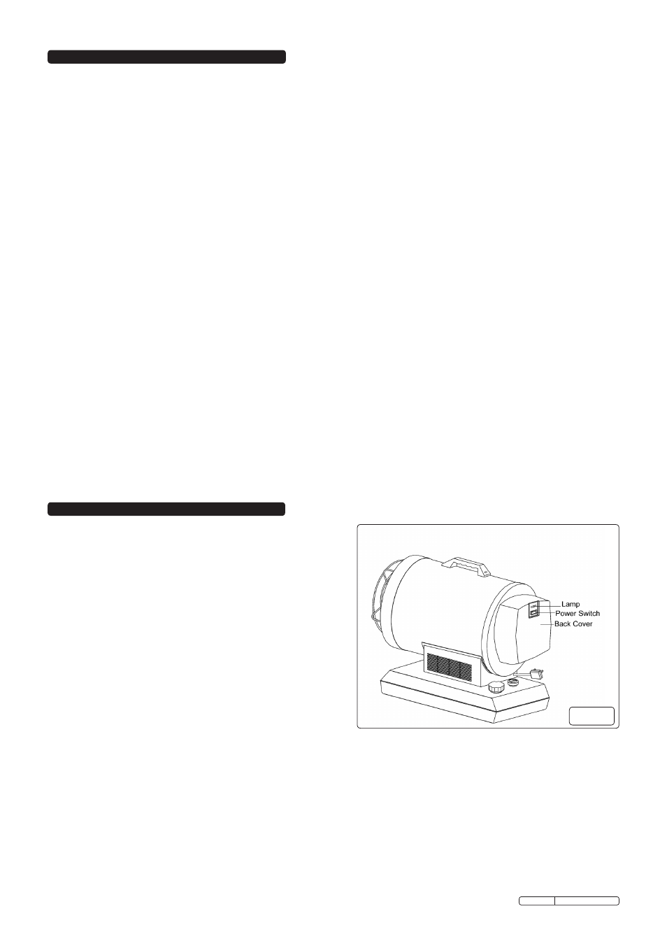
5.1.4. Push the Power switch (fig.2) to the "on" position.
NOTE! The electrical components of this heater are protected
by a fuse mounted on the Printed circuit board. If the
heater fails to fire, check this fuse first, and replace if
necessary. Also check the power source ensuring that the
correct voltage is being provided.
5.2.
TO STOP THE HEATER
5.2.1. turn the power switch (fig.2) to the "off" position. combustion will
stop and the cooling cycle (approx. 4-5minutes) will begin.
5.2.2. When cooling cycle has completed (fan stops running),
it is safe to unplug the heater from the mains supply.
WARNING! DO NOT DISCONNECT THE POWER SOURCE OR UNPLUG THE POWER CORD UNTIL THE COOLING CYCLE HAS
BEEN COMPLETED!
WARNING! UNPLUGGING THE UNIT BEFORE THE COOLING CYCLE HAS ENDED MAY CAUSE OvERHEATING, POSSIBLE
DAMAGE TO THE HEATER AND WILL vOID THE WARRANTY.
5.3.
TO RE-START THE HEATER
5.3.1. turn the Power switch to "on" position.
5.3.2. Be sure to follow all starting procedure precautions.
5. OPERATING INSTRUCTIONS
Fig.2
Original Language Version
Ir20.V2 Issue: 5 - 19/04/12