C2rps-psm cable -7, Power connectors on c2rps-psm (rear view) -7, Figure 2‐3 – Enterasys Networks C2RPS-SYS User Manual
Page 29: Figure 2‐4
Connecting the PSM Cables and AC Power Cords
SecureStack C2 Installation Guide 2-7
5.
On certain switches, an LED indicator will show that a redundant power supply is
now in operation.
.
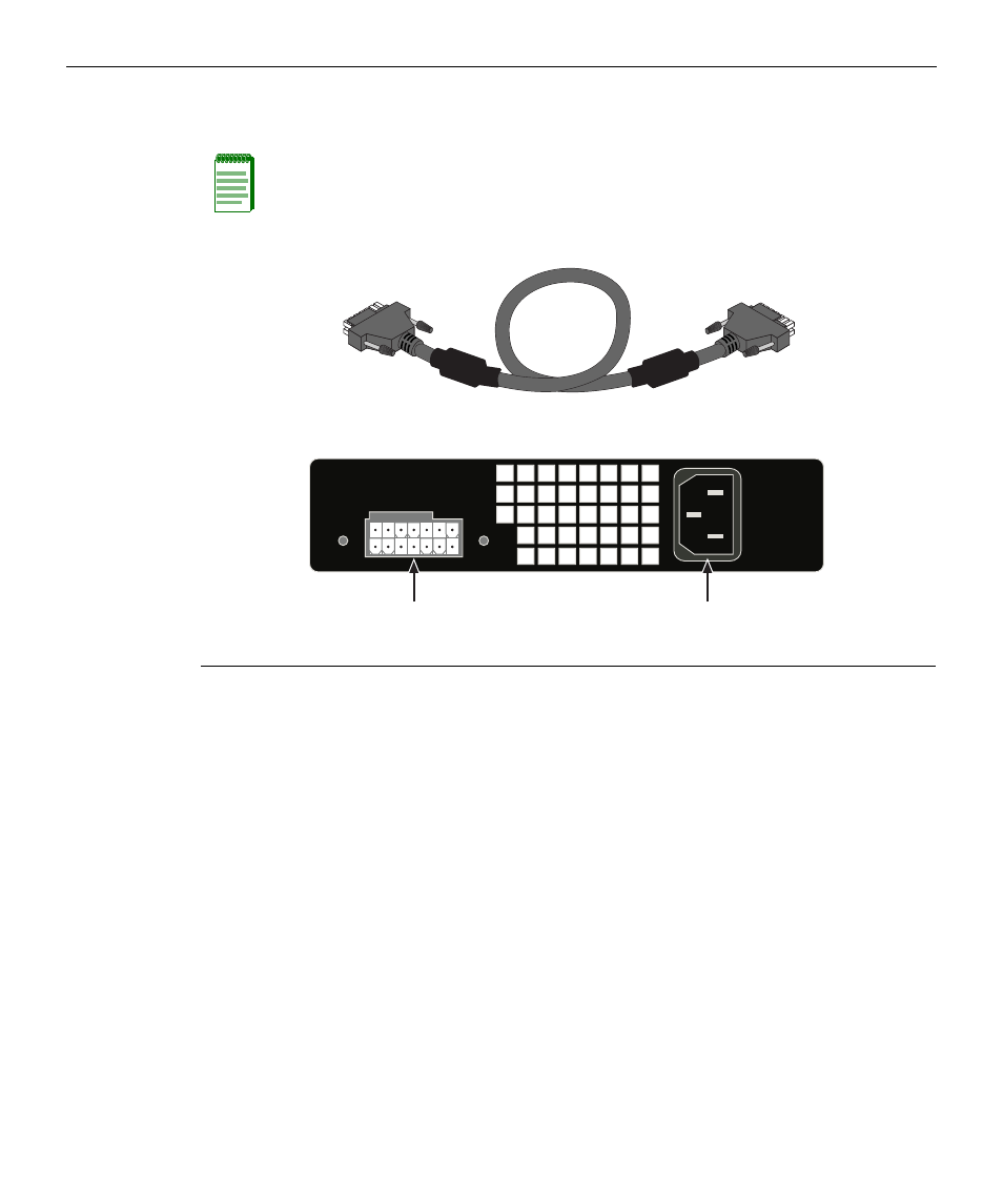
Figure 2-3 C2RPS-PSM Cable
Figure 2-4 Power Connectors on C2RPS-PSM (rear view)
Note: No change in switch configuration is necessary for this installation.
1 Redundant Power Supply connector
2 AC power connector (rear of chassis)
AC LINE
100-240 VAC
50-60 Hz
2A MAX
Redundant Power Supply
А
Б