Rps deployment strategies, Rps deployment strategies -4 – Enterasys Networks C2RPS-SYS User Manual
Page 20
RPS Deployment Strategies
1-4 Introduction
RPS Deployment Strategies
The RPS can be deployed in a variety of situations with mission‐critical applications.
For example:
•
For use in a voice and data network where switches are connected to IP phones and
PCs. Connecting an RPS to the switches can prevent voice network failures caused by
switch failures.
•
For use in traditional data 10/100/1000 Ethernet switches carrying mission‐critical
data.
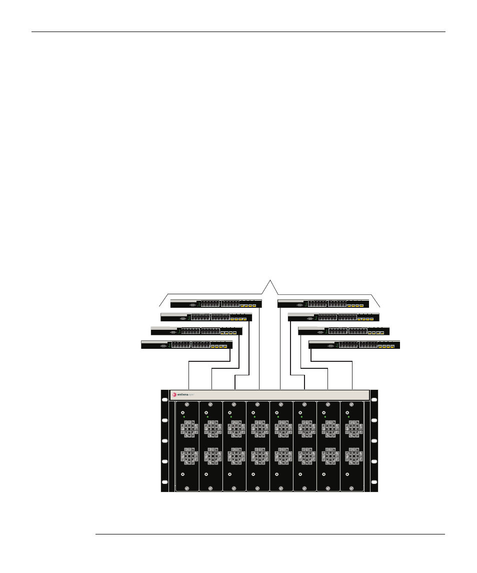
These applications would typically use one RPS to support up to eight SecureStack C2
switch devices as shown in
. If a SecureStack C2 switch device experiences an
internal power‐supply failure, the following occurs:
1.
The SecureStack C2 switch device internal DC‐power source is immediately switched
over from the internal DC‐power supply to the RPS DC‐power input.
2.
The SecureStack C2 switch device saves this status information for future retrieval, if
necessary.
Figure 1-5 RPS Supporting a Group of Switches (up to eight)
1 C2RPS-CHAS8 chassis (front view with eight PSMs)
3 SecureStack C2 Ethernet switches
2 C2RPS-PSM Cables for 12 Vdc and status
information from PSMs
А
В
Б
C2RPS-CHAS8
C2RPS-PSM
Po
w
er
C2RPS-PSM
Po
w
er
C2RPS-PSM
Po
w
er
C2RPS-PSM
Po
w
er
C2RPS-PSM
Po
w
er
C2RPS-PSM
Po
w
er
C2RPS-PSM
Po
w
er
C2RPS-PSM
Po
w
er
CONSOLE
1
2
23
24
21
22
23
24
CPU
UP
RPS
MASTER
DOWN
C2G124-24
CONSOLE
1
2
23
24
21
22
23
24
CPU
UP
RPS
MASTER
DOWN
C2G124-24
CONSOLE
1
2
23
24
21
22
23
24
CPU
UP
RPS
MASTER
DOWN
C2G124-24
CONSOLE
1
2
23
24
21
22
23
24
CPU
UP
RPS
MASTER
DOWN
C2G124-24
CONSOLE
1
2
23
24
21
22
23
24
CPU
UP
RPS
MASTER
DOWN
C2G124-24
CONSOLE
1
2
23
24
21
22
23
24
CPU
UP
RPS
MASTER
DOWN
C2G124-24
CONSOLE
1
2
23
24
21
22
23
24
CPU
UP
RPS
MASTER
DOWN
C2G124-24
CONSOLE
1
2
23
24
21
22
23
24
CPU
UP
RPS
MASTER
DOWN
C2G124-24