Optional blower installation instructions – Empire Comfort Systems CIVF-25-21 User Manual
Page 25
Page 25
16938-3-0806
Installing Optional CIB-2 Blower
1. Loosen, but do not remove, (4) hex-head screws located on
the exterior, bottom of the appliance.
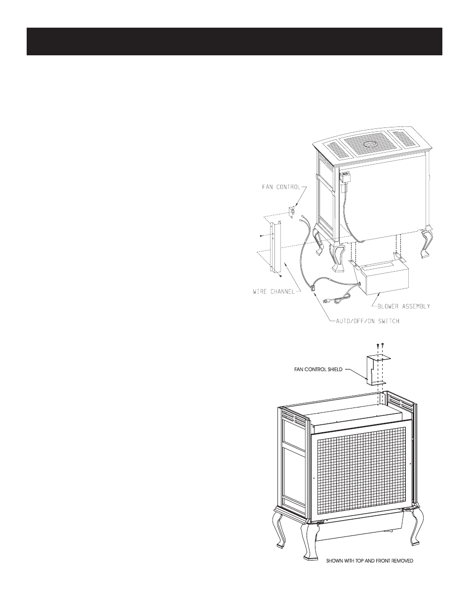
2. Position the blower assembly at the rear of the appliance.
The blower assembly has (4) keyholes for attachment to the
exterior, bottom of the appliance.
3. Place the large diameter holes in the keyholes over and behind
the (4) hex-head screws that were loosened in Step 1. Push
inward on the blower assembly to lock the keyholes into
position behind the screws. Tighten (4) hex-head screws to
secure blower assembly to exterior, bottom of the appliance.
(Refer to Figure 1)
4. Remove wire channel from rear cover by removing (4) hex-
head screws. Note: If optional blower is being installed during
initial installation of appliance, the wire channel will not be
attached to rear cover. (Refer to Wire Channel Installation,
Page 13)
5. Remove casting top and casting front from casting.
6. If optional stone inlay is installed in casting top, remove the
12" x 19 3/8" heat shield from the heat exchanger top by
removing (4) 1/2" hex-head screws.
7. When facing the rear of the appliance, insert fan control shield
between rear cover and inner body of appliance on the left
side of the rear cover.
8. Attach fan control shield to top of inner body with (2) #10 x
1/2" screw provided in hardware package. (Refer to Figure
2)
9. If applicable, attach 12" x 19 3/8" heat shield to heat exchanger
top with (4) 1/2" hex-head screws from Step 6.
10. Place the casing top onto the casting. The casting top nests
into the casting.
11. Attach fan control to FLAT, fan control bracket (Part 9A, Page
26) with (2) 6 x 1/4" screws provided in hardware package.
12. Attach fan control with bracket onto the wire channel by using
(2) 8 x 1/4" screws provided in hardware package.
13. Route wires from fan control and ON/OFF/REMOTE switch
within wire channel.
14. When facing the rear of the appliance, align and insert fan
control with bracket into 1 3/8" x 2" opening on the left side
of the rear cover.
15. Attach wire channel to rear cover by using (4) hex-head screws
removed in Step 4. (Refer to Wire Channel Installation,
Page 13)
16. Insert AUTO/OFF/ON switch into rectangular notch on valve
bracket. Be sure to insert AUTO/OFF/ON switch with letters
(words) upright. (See wiring diagram)
17. Attach 1/4" push-on terminal from blue wire on the fan control
to the AUTO (top) tab on the switch.
18. Attach 1/4" push-on terminal from black wire to the OFF
(middle) tab on the switch.
19. Attach 1/4" push-on terminal from white wire on the fan
control to the ON (bottom) tab on the switch.
20. Installation of optional CIB-2 blower is completed.
Fan Control
The fan control is a non-adjustable automatic type. The fan control
will require between 5 and 10 minutes of main burner operation
before the fan control "closes" and activates the blower. The blower
will continue to run between 5 and 10 minutes after the main
burner shuts off, before the fan control "opens" and deactivates
the blower.
OPTIONAL BLOWER INSTALLATION INSTRUCTIONS
Figure 1
Figure 2