Sensors, Manifold absolute pressure sensor, Manifold air temperature sensor – Edelbrock 3550 User Manual
Page 13
13
Pro-Flo EFI Installation Instructions
©2005 Edelbrock Corporation
Brochure No. 63-0115
Rev. 10/05
SENSORS
The Edelbrock Pro-Flo system interprets overall engine operating conditions and fuel/spark requirements based on readings from sensors that
measure specific engine conditions.
The Pro-Flo system includes five sensors:
1) Manifold Absolute Pressure
2) Manifold Air Temperature
3) Coolant Temperature
4) Throttle Position
5) Exhaust Oxygen (O
2
)
These sensors, with the exception of the O
2
, are designed as an integral part of the induction system and require no installation. The O
2
sensor
must be installed on the exhaust pipe near the engine with a welded fitting.
MANIFOLD ABSOLUTE PRESSURE SENSOR
The Manifold Absolute Pressure sensor, mounted on the air valve with a bracket, converts air
pressure (load) in the manifold, to an analog signal sent to the ECU. For more information on
Manifold Absolute Pressure, refer to the section on Speed Density Electronic Engine
Management. This sensor is connected to the Main System Harness by Connector J9.
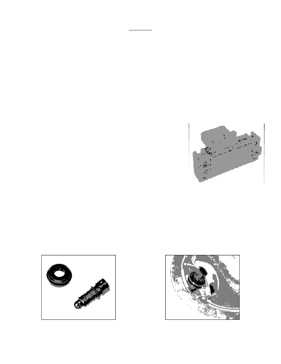
MANIFOLD AIR TEMPERATURE SENSOR
The Manifold Air Temperature sensor, is a thermistor device which measures air temperature. This sensor must be installed into
the air cleaner base. Drill the air cleaner base with a 3/4” drill, deburr any sharp edges, install MAT sensor grommet, then slide
sensor into grommet. This sensor is connected to the Main System Harness by connector J11.
NOTE: The systems that have the MAT sensor in the intake plenum area, can be moved to the air cleaner if necessary to obtain additional
vacuum ports.