Magnum Energy AC Load Diversion Controller (ACLD-40) User Manual
Page 14
Page 7
©
2015 Sensata Technologies
Introduction
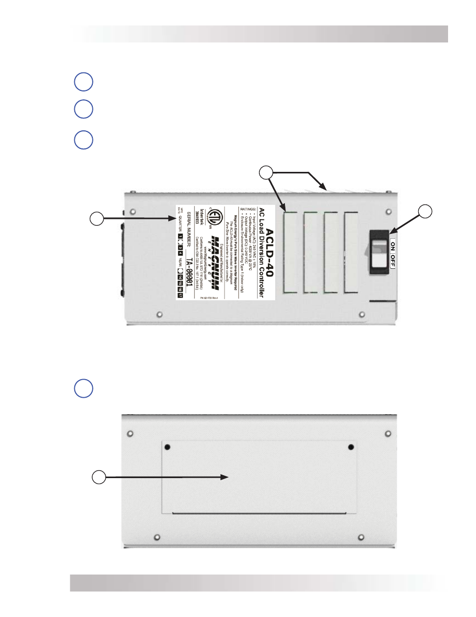
Figure 1-5, Wiring Access Cover
The left side of the ACLD controller has an access cover that can be removed (Figure 1-5):
9
Wiring Access Cover – provides access to the internal AC wiring terminal block and
ground busbar. This terminal block is used to hardwire all AC wiring connections.
Remove the two #6-32 screws to access the AC wiring terminal block.
Figure 1-4, ON/OFF Power Switch, Info Label and Exhaust Vents
The right side of the ACLD controller has an information label, exhaust vents and an ON/OFF
switch (see Figure 1-4):
6
Information Label – includes model/serial number information, date of manufacture,
and specifi cations. See the specifi cations in Appendix A for more information.
7
Exhaust Vents – ventilation openings that allow heated air to be removed by the internal
cooling fan. The exhaust air vents are located on the right side and at the rear of the top
side.
8
ON/OFF Power Switch – a power switch that turns the ACLD controller on or off.
9
Wiring
Access
Cover
Information
Label
Exhaust Vents
(on right and top sides)
ON/OFF
Power
Switch
8
7
6