Connection panels, Useful hints – Bang & Olufsen BeoSystem 3 Getting Started - No ATSC User Manual
Page 20
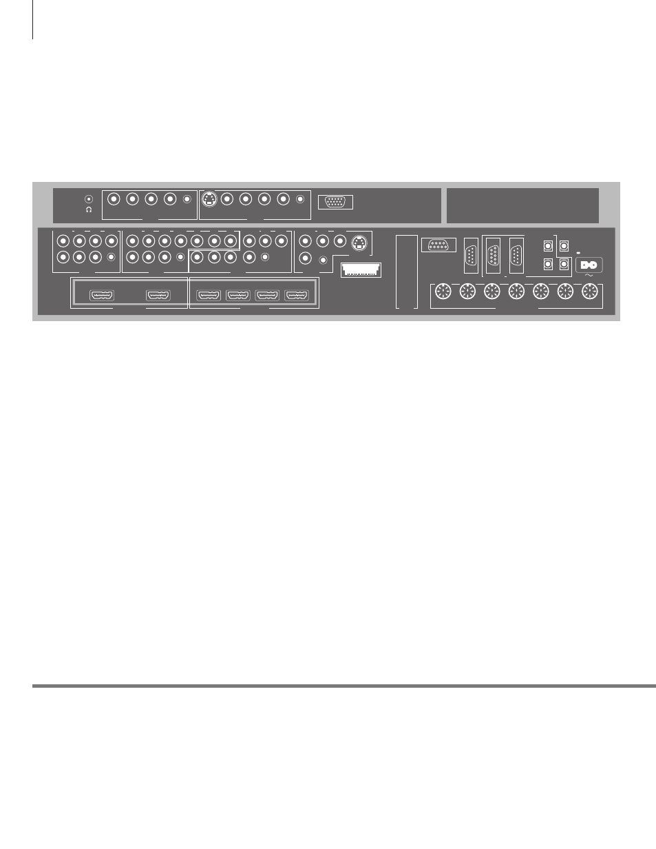
Connection panels
Any equipment you connect to the main connection panel must be registered in
the CONNECTIONS menu. Equipment connected to the side connection panel can
be registered in the CONNECTIONS menu.
Useful hints
Mains cord Connect the ~ socket on the main connection panel of your TV to the wall
outlet. The TV is in standby mode and ready to be used.
AV1
Socket group for AV connection of a primary
recorder or set-top box. You can also connect
other types of extra video equipment.
AV2
Socket group for AV connection of additional
video equip ment.
AV3
Socket group for AV connection of additional
video equip ment.
The TV keeps a signal path open between a
recorder connected to the AV1 socket and a
recordable source connected to the AV3 socket.
This allows you to set the source on AV3 to switch
on automatically, as well as set a recorder on AV1
for timed recording of the source on AV3,
provided your connected equipment supports
these functions.
AV4
Socket group for AV connection of additional
video equip ment.
AV5
Socket group for AV connection of additional
video equip ment. You can also connect a
BeoMaster, a camera or a camcorder.
AV6
Socket group for AV connection of additional
video equip ment. You can also connect a camera
or a camcorder.
CTRL (AV1 – AV6)
For IR control signals to external equipment
connected to an AV socket.
L-IN, R-IN (AV1 – AV6)
Right and left line input. AV5 and AV6 is for audio
connection of, e.g., a camera or camcorder.
L–R OUT (AV1 – AV2)
Right and left line output.
VIDEO IN (AV1 – AV6)
For video signal. On AV5 and AV6 you can
connect a camera or a camcorder.
VIDEO OUT (AV1 – AV2)
For a video recorder.
Y – Pb – Pr (AV2 – AV3)
For video signals from an external source, e.g.
HDTV source. You can use the socket in
conjunction with an AV socket or a digital audio
socket.
SPDIF (AV1 – AV6)
Digital audio input socket, e.g. DVD player.
S VIDEO (AV4, AV6)
For the connection of equipment with Y/C output,
e.g., a game console.
NOTE! Video recorders can only be connected to
the AV1 and AV2 socket groups, as these are the
only sockets groups for video output. Connect the
primary recorder to AV1 and the secondary
recorder to AV2.
POWER LINK
CONTROL
CENTRE 1
CINEMA
MONITOR
IR IN
DTV DATA
MASTER LINK
1(SUB)
2
3
4
TTL
5
6
HDMI IN
HDMI OUT
AV 4
AV 3
RS232
IR IN
CTRL
SPDIF
VIDEO IN L IN
R IN
IR 1+2
S VIDEO
VIDEO IN L IN
R IN
Y
Pb
Pr
AV 2
AV 5
AV 1
L IN
VIDEO IN
DISPLAY 1
R IN
SPDIF
L OUT
VIDEO
OUT
R OUT CTRL
R IN
L IN
VIDEO
IN
SPDIF
CTRL
DISPLAY 2
A
B
C
D
AV 6
R IN
L IN
VIDEO
IN
SPDIF
CTRL
VGA
S VIDEO
Pr
Pb
SPDIF CTRL
Y
L IN
VIDEO IN
R IN
SPDIF
L OUT R OUT
VIDEO
OUT
CTRL
20