Connection panels, Information – Bang & Olufsen BeoVision 11 with Beo4 Getting Started User Manual
Page 24
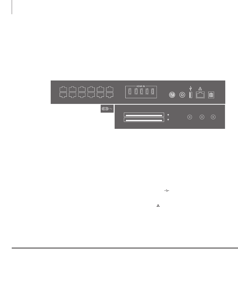
Connection panels
Any equipment you connect to the main connection panel must be registered in
the SOURCE LIST SETUP menu. Equipment connected to the top connection panel
can be registered in the SOURCE LIST SETUP menu.
Information
Connect the ~ socket on the main connection panel of your TV to the wall
outlet. The TV is in standby mode and ready to be used.
The supplied plug and mains cord are specially designed for the product. Do
not change the plug, and if the mains cord is damaged, you must buy a new
one from your Bang & Olufsen retailer.
~ – Mains supply
Connection to the mains supply.
PL 1–5 (Power link)
For connection of external speakers in a surround
sound setup. See the online guide for more
information.
MONITOR CONTROL
For future use.
PUC 1–3 A+B
For IR control signals to external equipment
connected to an HDMI IN or AV IN socket. Allows
you to control non-Bang & Olufsen equipment
with your Bang & Olufsen remote control.
CTRL (1–2)
For future use.
EXT. IR
For future use.
HDMI IN (1–5)
The High Definition Multimedia Interface allows
you to connect many different video sources, such
as set-top boxes, multimedia players, Blu-ray
players, or a PC.
AV IN
For connection of analogue video equipment.
S/P-DIF IN
Digital audio input socket, for example, a PC.
USB (
)
For connection of a USB device to browse digital
photos, video or music files.
Ethernet*
1
For connection to the Internet. For software
updates, access to WebMedia and PUC
downloads.
1
*Make sure the cable connection between the
product and the router does not exit the building
to avoid contact with high voltage.
Mains cord and plug
PL 5
PL 4
MONITOR
CONTROL
PUC 2
A+B
PUC 1
A+B
EXT. IR
PL 3
PL 2
PL1
PUC 3 A+B
CTRL 3
CTRL 2
CTRL 1
1
2
3
4
5
S/P-DIF
IN
STAND
AV
IN
CHIPSIDE
CHIPSIDE
AERIAL
SATELLITE
COMMON INTERFACE
2
1
24