Chapter 3, Board layout – Lanner LEC-7070 User Manual
Page 14
14
Board Layout
Chapter 3
Embedded and Industrial Computing
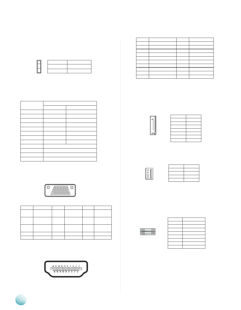
Clear CMOS jumper (CMOS1): It is for clearing the CMOS
settings.
LAN1/LAN2 Ports (LANB1/LANB2): The LAN ports are
provided by Intel 82583V Ethernet controller whose
interface complies with PCI-e 1.1 (2.5 Ghz). It supports PXE
remote boot as the advanced management feature
Pin No.
Description
Fast Ethernet Gigabit Ethernet
1
TX+
BI_DA+
2
TX-
BI_DA-
3
RX+
BI_DB+
4
--
BI_DC+
5
--
BI_DC-
6
RX-
BI_DB-
7
--
BI_DD+
8
--
BI_DD-
9
10-/100-/1000+
10
10+/100+/1000-
11
Link+/ACT-
12
Link-/ACT+
VGA (VGA1)
Pin
signal
Pin
signal
Pin
signal
1
Red Color
signal
6
GNd
11
NC
2
Green Color
signal
7
GNd
12
ddC dAT
3
Blue Color
signal
8
GNd
13
HsYNC
4
NC
9
VGA power
14
VsYNC
5
GNd
10
GNd
15
ddC CLK
HDMI Connector (HDMI1): High-Definition Multimedia
Interface Connector
Pin
signal
Pin
signal
1
dATA2+
2
GNd
3
dATA2-
4
dATA1+
5
GNd
6
dATA1-
7
dATA0+
8
GNd
9
dATA0-
10
CLK+
11
GNd
12
CLK-
13
N.C
14
N.C
15
ddC CLK
16
ddC dAT
17
GNd
18
HdMI_VCC
19
HPd
Serial-ATA Connector (SATA1): It is for connecting a 2.5’’
harddisk to serve as your system’s storage. It can support
SATA II which features Data transfer rates up to 3.0 Gb/s
(300 MB/s).
4-pin Serial-ATA Power Connector (PWR1): It is for
connecting the SATA power cord.
Dual USB Port Connector #0 and #1 (USB1):
Dual USB Port Connector #2 and #3 (USB2)
Pin No.
Pin Name
1-2
Normal (default)
2-3
Clear CMOs
1
2
3
Pin No.
Function
1
GNd
2
TX0_P
3
TX0_N
4
GNd
5
RX0_N
6
RX0_P
7
GNd
Pin No.
Function
1
NC
2
GNd
3
GNd
4
+5V
4
3
2
1
1 2 3 4 5
11 12 13 14 15
19 1
18 2
sATA1
7
6
5
4
3
2
1
1 2 3 4
5 6 7 8
Pin No.
Pin Name
1
UsB_VCC1
2
-UsB
3
+UsB
4
GNd
5
UsB_VCC2
6
-UsB
7
+UsB
8
GNd