Connectors and jumpers list, Chapter 3, Board layout – Lanner LEC-7070 User Manual
Page 12
12
Board Layout
Chapter 3
Embedded and Industrial Computing
Connectors and Jumpers List
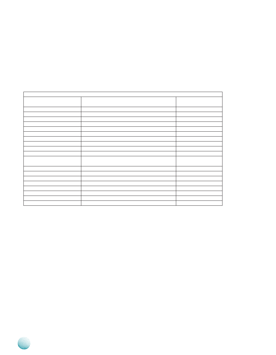
The tables below list the function of each of the board
jumpers and connectors by labels shown in the above
section. The next section in this chapter gives pin
definitions and instructions on setting jumpers.
Table 3.1 Connector List for LEB-7070 Board
Labels
Function
Pin Definition Refer-
ence Page
CMOS1
Clear CMOS Jumper
P14
COM1/COM2
RS232 Serial Ports
P13
DC_IN1
DC Power in
P15
DIO1
Digital Input/Output
P15
HDMI1
High-Definition Multimedia Interface Port
P14
KB1
PS/2 Keyboard & Mouse Connector
P15
LANB1/LANB2
Ethernet LAN Ports
P14
LIN1
Line-out Audio Jack
P13
LPC1
LPC Interface (for debug use only)
Reserved for Factory Use
MIC1
Microphone-in Audio Jack
P13
MPCIE1(with SIM1)/MPCIE2 (in
half length)
Mini-PCIe Connectors; MPCIE1(with SIM1 in full
length), MPCIE2 in half length
P15
PW_BTN2
Power Button with Phoenix Connector
P15
PWR1
SATA HDD Power Connector
P14
SC1T1/SC2T1
Select COM Port Pin 9 Function
P13
SATA1
Serial-ATA Connector (SATA1)
SPI1
SPI ROM Interface(for debug use only)
Reserved for Factory Use
USB1/USB2
USB Port 1-4 Connectors
P14
VGA1
VGA Connector
P14