English – Elektra Beckum TKHS 315 (AUS) User Manual
Page 10
10
ENGLISH
The cover is – same as the motor carrier
unit – hinge mounted at the two chip-
case guide panels. The heads of two
cap screws, fitted to the cover, serve as
swivel pin.
1.
Fit a distance sleeve (99) on a cap
screw (100), then put it from the out-
side into one of the cover's side pan-
els.
2.
Secure cap screw on the inside with
a prevailing torque-type nut (98).
3.
Place cover between the two chip-
case guide panels. The cap screw's
head must fit as illustrated into the Ø
10.5 mm hole in the chipcase guide
panel.
4.
Install the second cap screw with a
flange nut on the cover, so that its
head will likewise fit in the Ø
10.5 mm hole in the chipcase guide
panel.
5.
Insert guide bracket (101) into the
cover (102) as illustrated.
6.
Slide guide bracket so far in that the
bent end will hold the chipcase.
Fasten the guide bracket with two
pan head tapping screws (103) to
the chipcase.
Stand assembly
1.
Attaching the four legs (105) to the
inside of the table panel's corners:
− at the left front and rear of the
table top install the bracket (109)
for the mitre fence with extra
washers (110) as illustrated;
− fasten the hose carrier (111) as
illustrated;
− fit hexagon head screws (104)
into holes from the outside;
− from the inside screw on flange
nuts (107) – do not yet tighten
fully.
2.
Fit long stanchions (108) between
the side legs, short stanchions (106)
between the front and rear legs:
− the wide sides of the stanchions
face the table panel;
− the nibs and recesses must fit
into each other;
− fit hexagon head screws (104)
into holes from the outside;
− from the inside screw on flange
nuts (107) – do not yet tighten
fully.
3.
Screwing up the stanchions with
each other:
− Fit hexagon head screws (104)
from the side of the table top;
− from the inside screw on flange
nuts (107) – do not yet tighten
fully.
− With the help of another person,
turn the saw over and stand it on
a level floor.
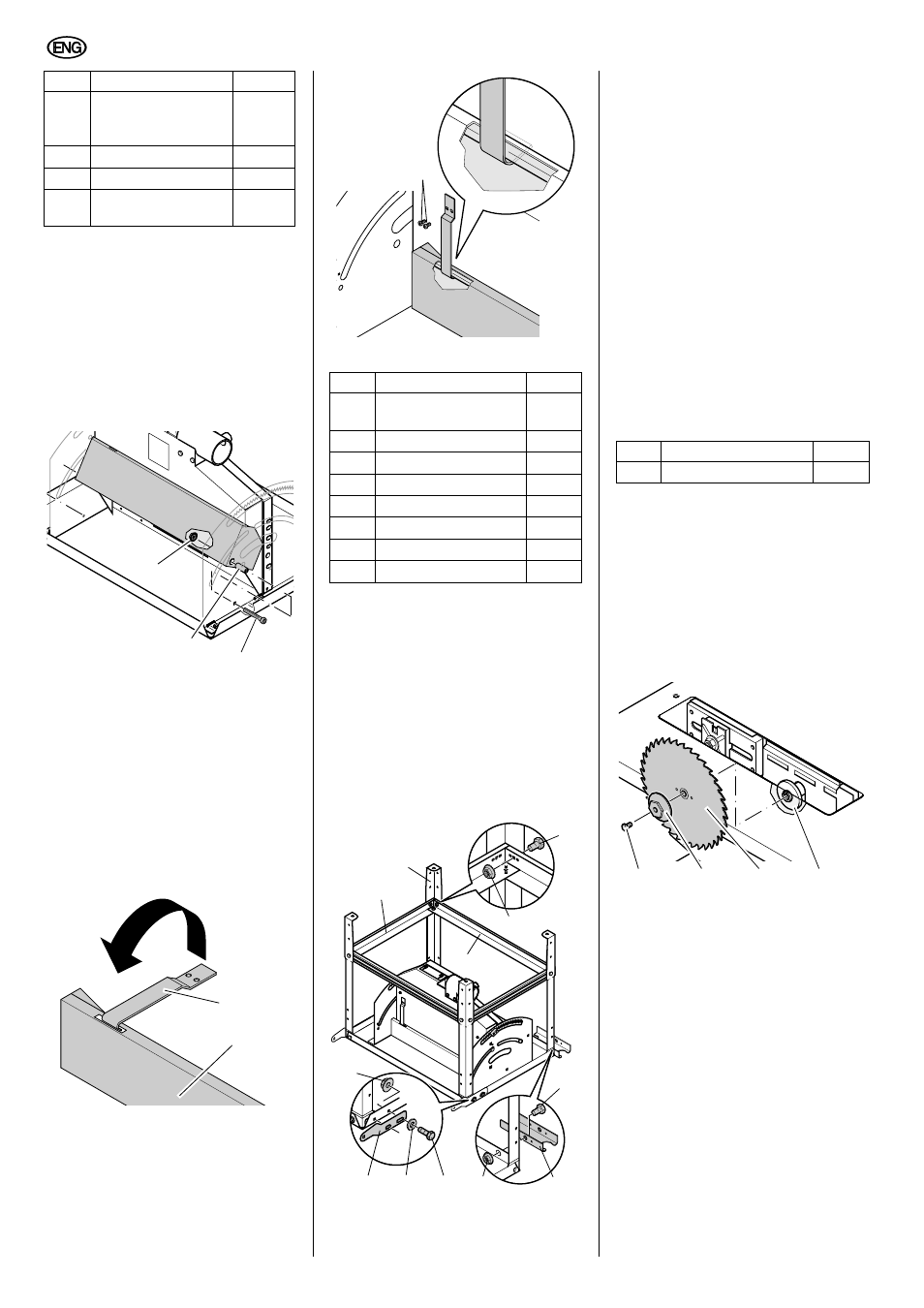
Saw blade installation
A
Danger!
Cutting hazard by the saw
blade: wear gloves when fitting a saw
blade.
1.
Raise motor fully.
2.
Unscrew arbor bolt (112) from the
saw spindle (L.H. thread!) and
remove the outer blade collar (113).
3.
Fit saw blade (114), observe run-
ning direction of teeth.
4.
Put on outer blade collar (115) (the
inner blade collar's lug must engage
in the groove of the outer blade col-
lar (113)).
5.
Screw arbor bolt (112) back in the
saw spindle (L.H. thread!) and
tighten it. Hold outer blade collar
(115) with ring spanner to counter.
A
Caution!
Always hold the saw blade with
the ring spanner SW 46 at the outer
blade collar, never by any other
means (e.g. with pliers).Otherwise the
saw blade will be damaged.
A
Risk of injury!
After the arbor bolt has been
tightened, remove all tools used dur-
ing saw blade installation!
Hex. socket counter-
sunk head screw
M6 x 25
2
Guide bracket
1
Cover
1
Pan head tapping
screw
∅3.9 x 9.5
2
Item
Description
Qty.
98
99
100
101
102
Item
Description
Qty.
Hexagon head screw
M8 x 16
20
Leg
4
Stanchion, short
2
Flange nut M8
20
Stanchion, long
2
Bracket for mitre fence
2
Washer 8.4/17
4
Hose carrier
1
103
106
109
108
105
110
104
107
111
Item
Description
Qty.
Saw blade
∅315 mm
1
115
112
113
114