Chapter 2, System components – Lanner LEC-6020 User Manual
Page 9
9
System Components
Chapter 2
Embedded and Industrial Computing
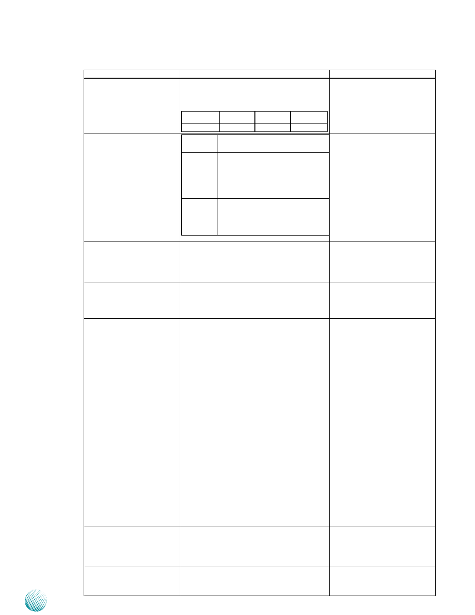
Component
Description
Pin Definition Reference
F2 Serial Port LED
These two rows are LED indicators of Tx (Data
transmitting in yellow) and RX (Data receiving
in yellow) for serial port status.
RX-COM 2 TX-COM 2 RX-COM 3 TX-COM 3
RX-COM 4 TX-COM 4 RX-COM 5 TX-COM 5
F3 HDD/RUN/PWR LED
Power
Green indicates Power-on, where
as Off indicates Power-off status.
Run
A programmable dual green/
orange LEDs which can be used
for indicating system status. For
sample code, please look into
your Driver and User Manual CD.
HDD
Blinking indicates hard disk
activities, whereas Off indicates
there is no hard disk present or
data access activities.
F4 Programmable LEDs
These three LEDs are programmable and can
be controlled by SW1.
SW1 on page 17
F5 Four or Two USB 2.0 Ports
(Two ports on model B, C, D)
An USB type A connector. Model 6020A pro-
vides two extra ports from the daughter
board.
USB1/USB2 on page 17; USB2/
USB3 on page 19
F6 Three10/100/1000Mbps
LAN ports (5 on model B, D,
7 on model C)
LEC-6020A: Three RJ-45 (network) connectors
LAN1~LAN3 ports are provided by Intel
82574L; LAN1 and LAN2 are capable of
bypass. LAN3 supports WOL/PXE functions.
(The default setting for PXE is disable; enable
it in the BIOS menu.) .
LEC-6020B: It supports two pairs of
LAN bypass (LAN1-LAN2, LAN3-LAN4).
LAN1~LAN5 ports are provided by Intel
82574L. And LAN5 supports WOL/PXE. (The
default setting for PXE is disable; enable it in
the BIOS menu.)
LEC-6020C: Five RJ-45 and two optical fiber
connectors. LAN1/LAN2 ports are provided
by Intel 82574L while LAN3~LAN5 as well
as the two fiber ports are provided by Intel
I210. LAN1 and LAN2 are capable of bypass.
LAN3~LAN5 support WOL. (The default
setting for WOL is enable.)
LEC-6020D: Five RJ-45 connectors.
LAN1~LAN5 ports are provided by Intel
82574L; LAN1 and LAN2 are capable of
bypass. LAN3~LAN5 support WOL/PXE (The
default setting for PXE is disable; enable it in
the BIOS menu.)
LAN1~LAN3 (of LEK-6020EN2/
EN2B) on page 21;
LANB1~LANB3 and SFP1~SFP2
(of LEK-6020F1)on page 22
F7 COM Port (on model C,D) COM Port
The default terminal configurations:
115200 baud rate, 8 data bits, no parity, 1
stop bit , no flow control.
COM1 (of LEB-6020) on page 18
F8 FX1, FX2 LEDs (
LEDs for the Fiber ports status.
Blinking: port is active
Yellow: port is linked