Chapter 2, System components, Block diagram – Lanner LEC-6020 User Manual
Page 7
7
System Components
Chapter 2
Embedded and Industrial Computing
Block Diagram
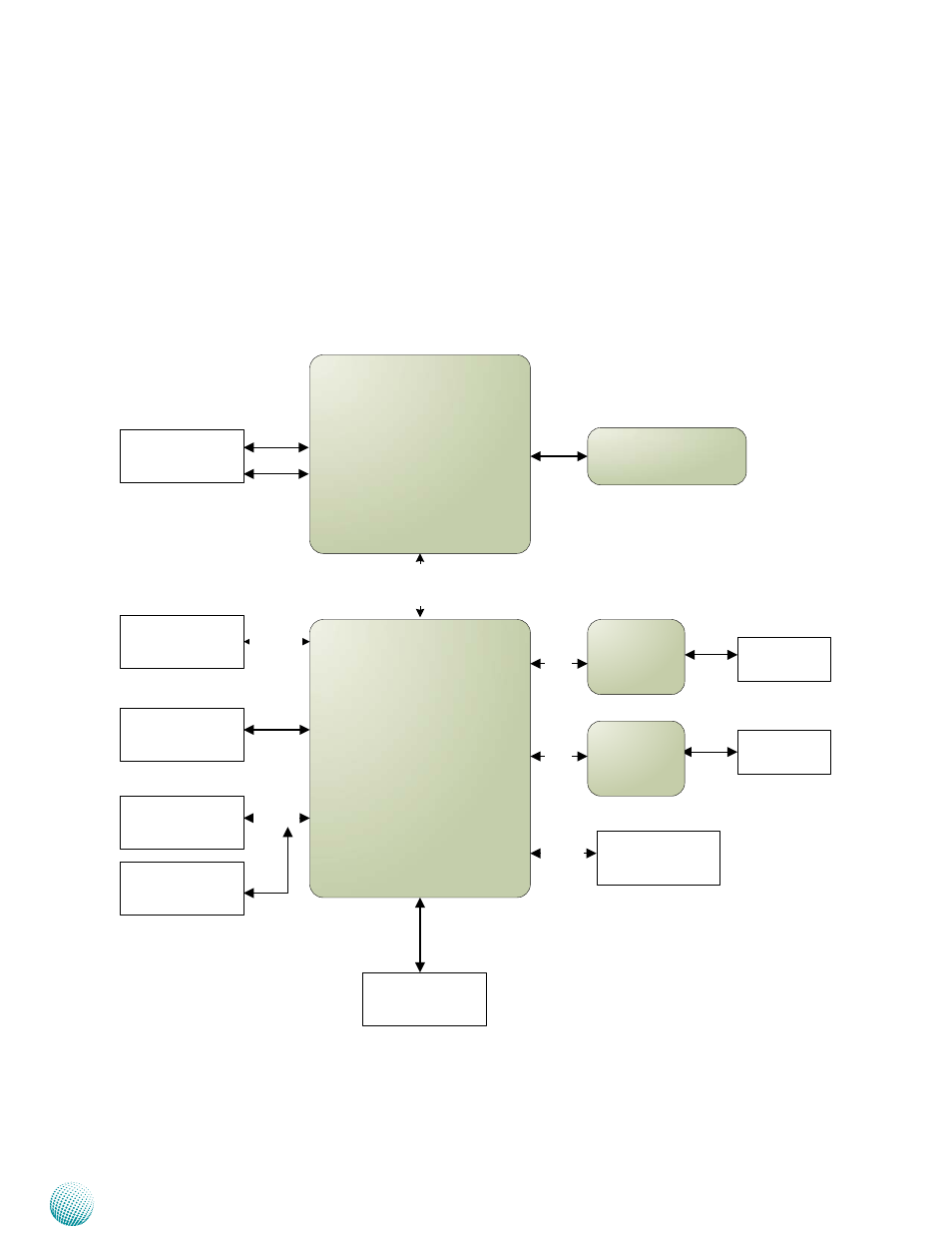
The block diagram depicts the relationships among the
interfaces and modules on the motherboard.
DDRIII 1066/1333 MHz
1x SO-DIMM
GbE Controller
Intel 82574L
Processor
Cedarview CPU
N2600
Intel
NM10
PCIe
X4
D
M
I
VGA
SATA Connector
Keyboard/Mouse
Pin Header
USB 2.0
2x Type A
SATA 2.0
LPC I/O
(627HF)
USB2.0
LAN 1
LAN 2
GbE Controller
Intel 82574L
PCIe
CompactFlash II
Socket
Console
Pin Header
Extension Bus