Chapter 3, Board layout, Jumper settings – Lanner LEC-6020 User Manual
Page 17
17
Board Layout
Chapter 3
Embedded and Industrial Computing
Jumper Settings
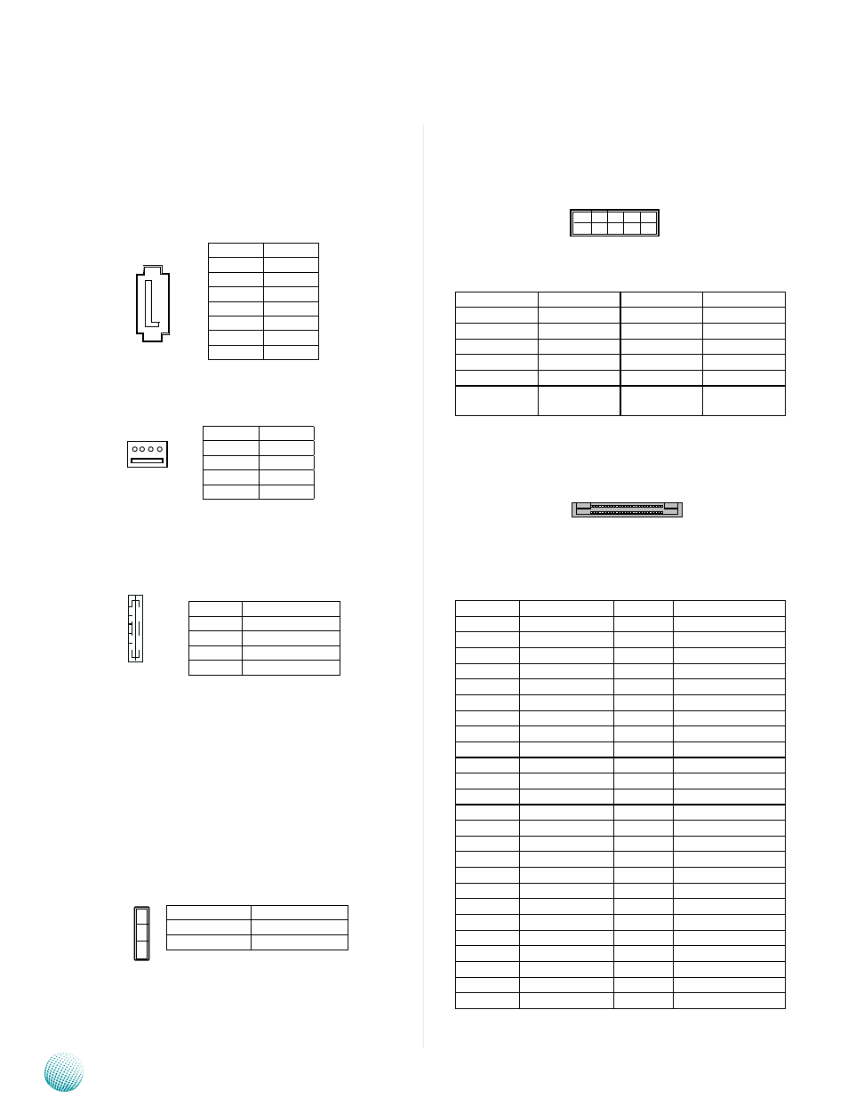
Serial-ATA Connector (SATA1): It is for connecting a
2.5’’ harddisk to be served as your system’s storage. It can
support SATA II which features Data transfer rates up to 3.0
Gb/s (300 MB/s).
4-pin Serial-ATA Power Connector (CON1): It is for
connecting the SATA power cord.
USB Port (USB1, USB2):
Reset Button (RST1)
LED2 Control Button (SW1): This control button is a
programmable button to control the behavior of the three
LEDs of LED2.
HW/SW Reset (RST2)
Pin No. Function
1
GND
2
TX+
3
TX-
4
GND
5
RX-
6
RX+
7
GND
LEB-6020
Pin No. Function
1
12V
2
Ground
3
Ground
4
5V
1 2 3 4
VGA Port (VGA1)
Pin No.
Description
Pin No.
Description
1
CON_RED
2
CRT_ON
3
CON_GREEN
4
GND_VGA
5
CON_BLUE
6
GND_VGA
7
CON_HSYNC
8
GND_VGA
9
CON_VSYNC
10
GND_VGA
11
CON_DDC_
DAT
12
CON_DDC_
CLK
Compact Flash Connector (CF1)
PIN
Description
PIN
Description
1
GND
26
DET1
2
CF_DD3
27
CF_DD11
3
CF_DD4
28
CF_DD12
4
CF_DD5
29
CF_DD13
5
CF_DD6
30
CF_DD14
6
CF_DD7
31
CF_DD15
7
-CF_DCS0
32
-CF_DCS1
8
GND
33
CF_VS1
9
GND
34
CF_DIOR_N
10
GND
35
CF_DIOW_N
11
GND
36
P3V3S
12
GND
37
CF_IDEIRQ
13
CF_PW
38
CF_PW
14
GND
39
MST_SLV
15
GND
40
CF_VS2
16
GND
41
CF_IDERST_N
17
GND
42
CF_IORDY
18
CF_DA2
43
CF_DMARQ
19
CF_DA1
44
CF_DDACK_N
20
CF_DA0
45
CFACT_N
21
CF_DD0
46
CF_PDIAG
22
CF_DD1
47
CF_DD8
23
CF_DD2
48
CF_DD9
24
NC
49
CF_DD10
25
CF_DIS_N
50
GND
Pin No.
Pin Name
1
VCCUSB01
2
USB0N_REAR_L
3
USB0P_REAR_L
4
GND
1
2
3
4
5
6
7
4
3
2
1
1
2
11
12
Pin No.
Pin Name
1-2
Software Reset
2-3 (Default) Hardware Reset
1
2
3