Chapter 3, Motherboard information – Lanner MR-730 User Manual
Page 15
12
Motherboard Information
Chapter 3
Network Application Platforms
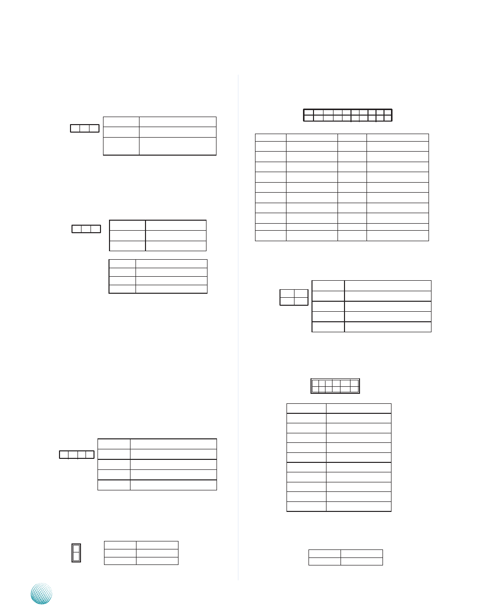
Bootloader Mode Selector(JP1): It is a jumper
for selecting the bootloader mode from either normal
or fail-safe mode.
Flash Mode Selector(JP4): It is a jumper for
selecting the flash mode from either normal or Net
mode. The Net mode is for debugging purpose.
Adjust this jumper to the Net mode when connecting
NetROM connector (NETROM1).
DIMM Socket (DIMM1/DIMM2): The 240-pin
DIMM is for connecting the DDR2 533/667/800 MHz,
ECC Registered memory. The system can support up
to a maximum of 4GB for DDR2 533/667 and 2GB for
DDR2 800.
SATA Driver Connector (SATAB1, SATAB2): It is
for connecting a 2.5’’ SATA harddisk to be served as
your system’s storage. The system can support up to
2 disks of 2.5” in maximum.
Serial-ATA Power Connector (SATAPCN1,
SATAPCN2): It is used for connectig the SATA power
cord.
Power-on Switch Connector (J2): It is a power
switch without overheating protection which is for
debug purpose only.
20 Pin ATX Power Connector (ATX1): It is used for
connecting the power supply to the board.
4 Pin ATX Power Connector (ATX2): It is used for
connecting the power supply to the board.
Front LCD Module Connector(COMB1): The 10-
pin connector is for connecting the front system LCD
panel.
Power-on Switch Connector (J3): It is for
connecting the power switch to the back panel.
Pin No.
Mode
Short 1-2
Failsafe
Short 2-3
Normal (default)
0 X 40000
Pin No.
Jumper Selection
Short 1-2 Normal (default)
Short 2-3
Debug
3 2 1
3 2 1
Pin No.
Function
1
FLASH_BOOT_CS#
2
BOOT_CS#0
3
NETROM_CS#
4 3 2 1
Pin No.
Function
1
+12V
2
GND
3
GND
4
5V
Pin No.
Function
1
GND
2
PS_ON_L
1
2
Pin No.
Function
1
NC
2
NC
3
RS232_1_SIN
4
RS232_1_RTS
5
RS232_1_SOUT
6
RTS232_1_CTS
7
NC
8
NC
9
GND
10
NC
PIN NO.
FUNCTION
PIN NO.
FUNCTION
1
+3.3V
11
+3.3V
2
+3.3V
12
-12V
3
Ground
13
Ground
4
+5V
14
PSON-
5
Ground
15
Ground
6
+5V
16
Ground
7
Ground
17
Ground
8
Power Good
18
NC
9
Stand-By 5V
19
+5V
10
+12V
20
+5V
1 3 5 7 9 1 1 1 3 1 5 1 7 1 9
2 4 6 8 1 0 1 2 1 4 1 6 1 8 2 0
2 1
4 3
Pin No.
Function
1
GND
2
+12V
3
GND
4
+12V
1 3 5 7 9
2 4 6 8 1 0
Pin No.
Function
Short 1-2
Power on