Motherboard layout, Chapter 3, Motherboard information – Lanner MR-730 User Manual
Page 13
10
Motherboard Information
Chapter 3
Network Application Platforms
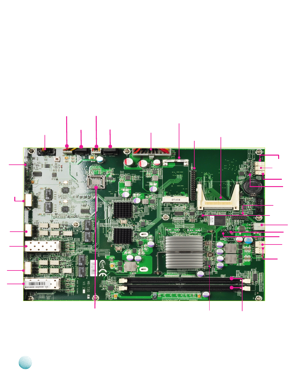
Motherboard Layout
The motherboard layout shows the connectors and
jumpers on the board. Refer to the following picture
as a reference of the pin assignments and the internal
connectors.
10/100/1000
LAN PORT (RJ2)
Front LCM
Connector (COMB1)
DIMM1
DIMM2
Mini PCI-E Connector (MPCIE1)
CF Card
(CF1)
NetROM Connector
(NetROM1)
Power-On Switch
Connector (J3)
Power On
Switch for de-
bug use only
(J2)
JTAG Connector
(JTAG1)
Bootloader Address
Selection (JP1)
GPIO (J1)
Reset Switch
Button (SW2)
Power Failure
Alarm (CONN1)
Power Failure
Alarm (CONN2))
4 Pin ATX Power
Connector (ATX2)
FAN Connector
(FAN1)
FAN Connector
(FAN2)
S A T A D i s k
C o n n e c t o r
(SATAB1)
S A T A D i s k
C o n n e c t o r
(SATAB2)
S A T A P o w e r
C o n n e c t o r
(SATAPCN1)
S A T A P o w e r
C o n n e c t o r
(SATAPCN2)
20 Pin ATX
Power Connec-
tor (ATX1)
Flash Mode
Selector(JP4)
R O M f o r
RAID function
of SATA
10/100 Mgm
PORT (RJ1)
SFP PORT (CN1))
SFP PORT (CN2)
10/100/1000
LAN PORT (RJ3)
SW1