Chapter 3: motherboard information, Block diagram, Chapter 3 – Lanner MR-301 User Manual
Page 9: Motherboard information
6
Motherboard Information
Chapter 3
Network Application Platforms
Chapter 3:
Motherboard Information
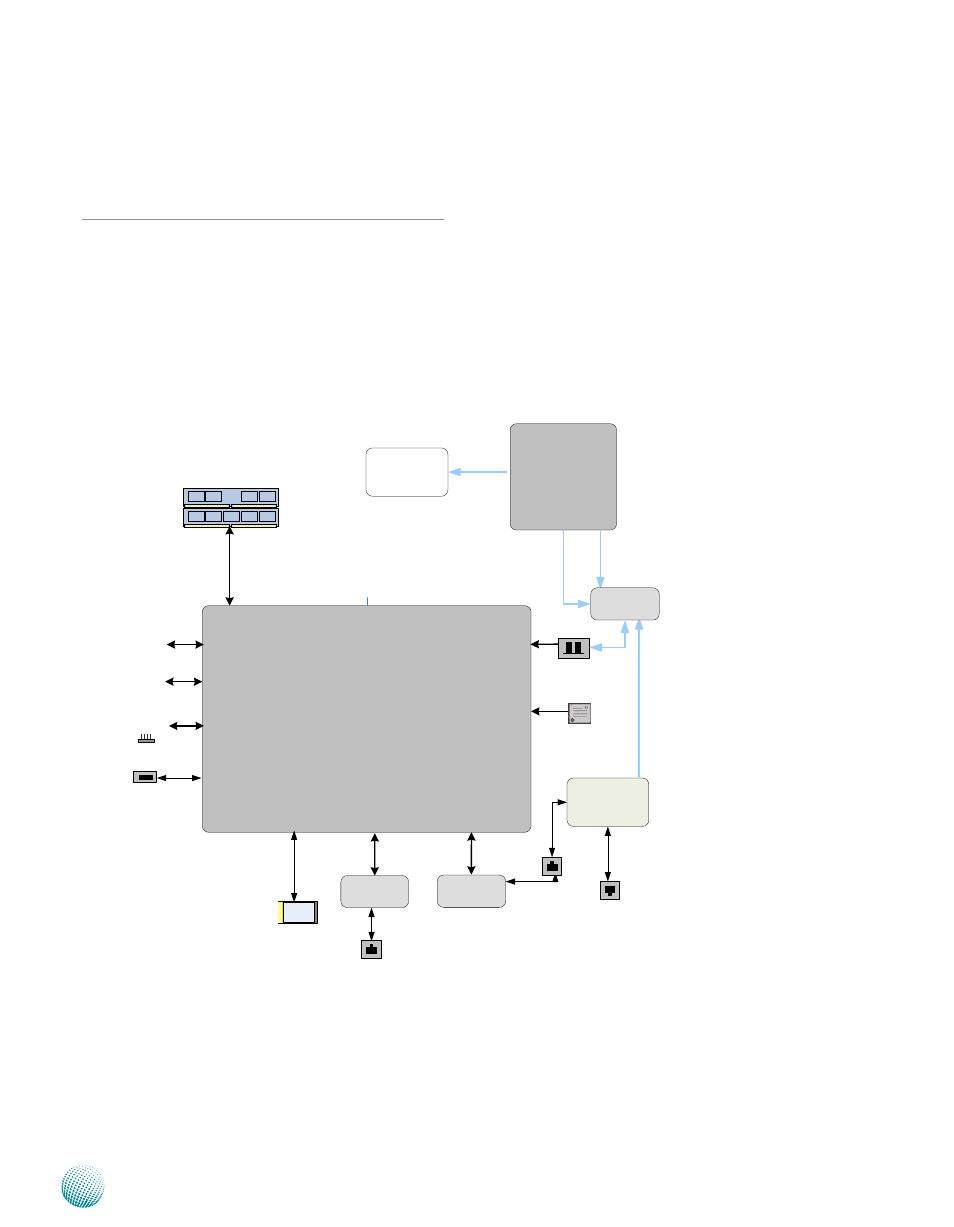
Block Diagram
The block diagram depicts the relationships among the
interfaces or modules on the motherboard. Please refer
to the following figure for your motherboard’s layout
design.
Power via
DC-in 12V
Marvell Shiva 88F6281
U
A
RT
2
5 x GbE RJ-45
Connectors w/ LED
1 x PCIe bus
DDR2
Channel
1 x 2.5"
HD Bay
NAND Flash
64MB
USB
Connector
USB
2.0
2x
S
A
TA
II
1 SATA Port
DDR2 512MB
onboard memory
Serial Pin
Header
Marvell
88E6161
Marvell
88E1116
NAND
MB-301
RGMII
CP
U
JT
A
G
CPU JTAG
G
PIO
Reset Button
System
Fan
5V
5V
12V
ADSL
Modem
RJ11
RJ45
RGMII
Mini PCI-E Connector
12V
SATA Power
See also other documents in the category Lanner Computer hardware:
- LVC-2000 (39 pages)
- LVC-5000(N4) (42 pages)
- LVC-5550S (41 pages)
- LVC-5570 (48 pages)
- LVC-5770 (49 pages)
- FW-6432 (16 pages)
- FW-7525 (41 pages)
- FW-5330 (38 pages)
- FW-6486 (18 pages)
- FW-6436 (19 pages)
- FW-7573 (44 pages)
- FW-7568 (52 pages)
- FW-7540 (47 pages)
- FW-8759 (47 pages)
- FW-7581 (23 pages)
- FW-8758 (42 pages)
- FW-7610 (44 pages)
- FW-8756 (24 pages)
- FW-7575 (48 pages)
- FW-8760 (53 pages)
- FW-8877 (46 pages)
- FW-8892 (58 pages)
- FW-8893C (49 pages)
- FX-3411 (48 pages)
- FW-8894 (31 pages)
- FW-8771 (47 pages)
- RS12-38800 (64 pages)
- MR-320 (20 pages)
- FX-3210 (54 pages)
- MR-350 (12 pages)
- MR-330A (16 pages)
- MR-730 (18 pages)
- VES-220 (19 pages)
- VES-270 (19 pages)
- VES-310 (15 pages)
- VES-310 V2 (20 pages)
- VES-500 (21 pages)
- EM-F345 (30 pages)
- VES-8X2 (16 pages)
- VES-8X6 (17 pages)
- LEC-2026 (67 pages)
- LEC-2010 (65 pages)
- LEC-2136 (20 pages)
- LEC-2050 (38 pages)