Front panel features, Chapter 1, Introduction – Lanner MR-301 User Manual
Page 6
3
Introduction
Chapter 1
Network Application Platforms
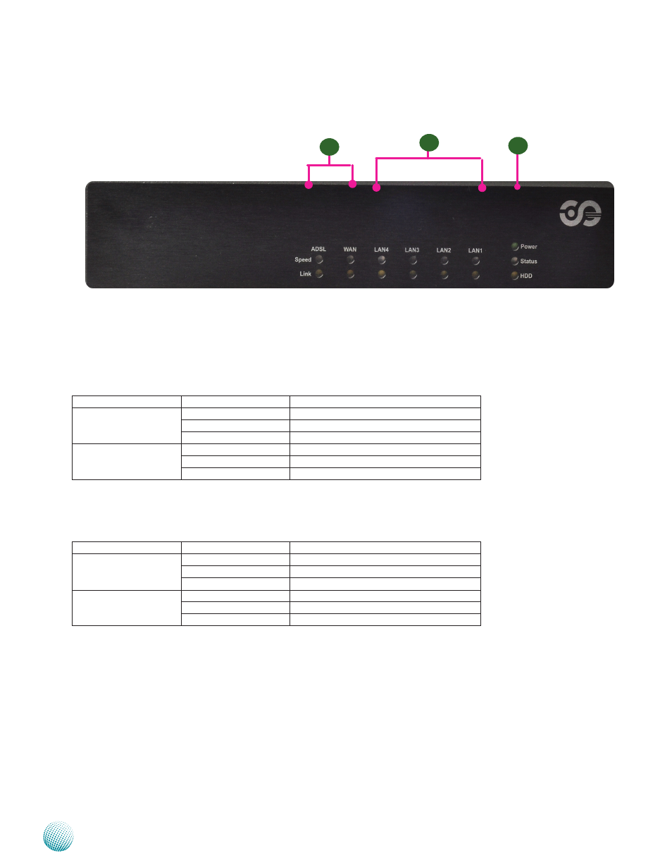
Front Panel Features
F1 LED Indicators for ADSL and WAN
The ADSL LED indicates the connection status of the ADSL services, whereas the WAN LED indicates the connection status
of the Internet service.
Speed LED (Green/Amber):
LED
Behavior
Interpretation
LINK/ACT (Yellow)
On/Flashing
The port is linking.
Off
The port is not linking.
SPEED (Green/Amber)
Amber
The connection speed is 1000Mbps.
Green
The connection speed is 100Mbps.
Off
The connection speed is 10Mbps.
F2 LED Indicators for 4 LANs
The LAN4/LAN3/LAN2/LAN1 LED indicates the connection between the port and the next piece of network equipment.
LED
Behavior
Interpretation
LINK/ACT (Yellow)
On/Flashing
The port is linking.
Off
The port is not linking.
SPEED (Green/Amber)
Amber
The connection speed is 1000Mbps.
Green
The connection speed is 100Mbps.
Off
The connection speed is 10Mbps.
F3 Power/Status/HDD LED
Power LED (Green):
Green indicates that the system is powered on.
Status LED (Green/amber):
This LED is programmable. You could program it to display the operating status with the behavior like the following:
If the LED is green, it indicates that the system’s operational state is normal. If it is amber, it indicates that the system is
malfunctioning. For sample code, refer to the Drive and Manual CD.
HDD LED (Yellow):
It is an LED indicator for the hard disk. If it is flashing, it indicates data access activities. Otherwise, it remains off.
F3
F2
F1