Chapter 3, Motherboard information – Lanner MR-301 User Manual
Page 13
10
Motherboard Information
Chapter 3
Network Application Platforms
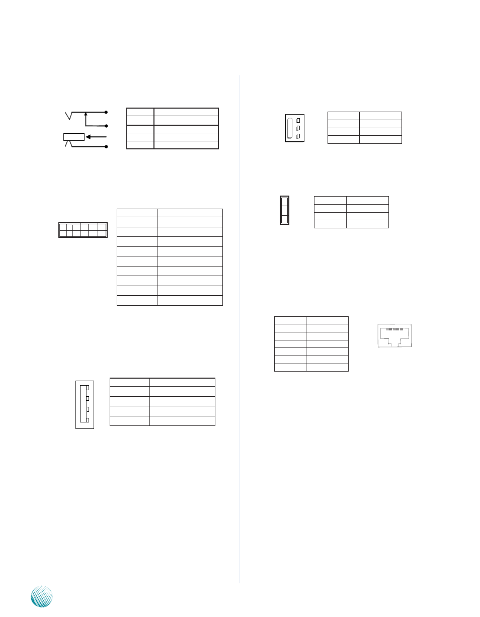
12V DC Power Jack (J1): It is used for
connecting the power adaptor to the board.
Intel Serial port UART1 Connector (J6): The
10-pin connector is for connecting RS-232 serial
devices. This port is assigned as COM2 whereas the
console port is assigned as COM1.
USB Port (J2): It is for connecting the USB
devices. It complies with USB 2.0 and can
support 480 Mbit/s Mbps transmission rate.
System FAN Connector(FAN1/FAN2): This 3-pin
header is for connecting the system fan.
GPIO Pin Header (J14)
Telephone Port (RJ1 on the front panel to
connecting to the telephone port , RJ2 on the internal
connector): The front panel (RJ1) port is used to connect
to the telephone line to your local telephone system with
DSL services and. The internal RJ2 port is used to connect
to the DSL module installed on the system.
Pin No.
Function
1
NC
2
NC
3
SERIAL1_RXD_R
4
NC
5
SERIAL1_TXD_R
6
NC
7
NC
8
NC
9
BP_GND
1 0 8 6 4 2
9 7 5 3 1
3
2
1
4
Pin No.
Function
1
VCC12_IN
2
GND
3
GND
4
GND
J2
4
1
Pin No.
Function
1
V_Vbus
2
Usb0_n
3
Usb0_p
4
BP_GND
1
2
3
Pin No.
Function
1
V_3.3
2
Mpp36
3
GND
Pin No.
Function
1
Tx_F
2
Tx
3
Tx_G
4
Rx_G
5
Rx
6
Rx_Fl
1 2 3 4 5 6
Pin No.
Function
1
GND
2
V_12
3
FAN SPEED
3
2
1