Chapter 3, Motherboard information – Lanner FW-7581 User Manual
Page 14
11
Motherboard Information
Chapter 3
Network Application Platforms
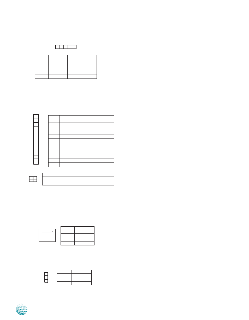
ATX Power Connector(ATX1, ATX2): These 24-pin and
4-pin connectors are for connecting ATX power supply
plugs. Find the proper orientation when inserting the
plugs, for the supply plugs are designed to fit these
connectors in only one orientation.
CPU Fan Connectors(FAN1/FAN2/FAN3/FAN4): 4-pin
connector for connecting the smart fan. Connect CPU
fans to FAN1 and FAN2; connect system fan to FAN 3. FAN1
and FAN2 will be referred to as CPU fans and FAN3 will be
referred to as system fan on the Smart Fan control menu in
the Hardware Health Configuration of the BIOS.
System Fan Connector (FAN5): 3-pin connector for
connecting the system fan. This one doesn’t have a smart
fan feature.
CPU Socket: The LGA 775 socket is for connecting the
CPU.
Pin No.
Function
1
GND
2
FAN
3
FINA
4
FINB/NA
Pin No.
Function
1
GND
2
+12V
3
NC
Pin No.
Function
PIN NO. DESCRIPTION
1
3.3V
2
3.3V
3
3.3V
4
-12V
5
GND
6
GND
7
5V
8
PSON
9
GND
10
GND
11
5V
12
GND
13
GND
14
GND
15
POK
16
-5V
17
5VSB
18
5V
19
12V
20
5V
21
12V
22
5V
23
3.3V
24
GND
1
3
5
2 3
2
4
6
24
Pin No.
Pin name
Pin No.
Pin name
1
Ground
2
P12V_A
3
Ground
4
P12V_A
1
2
3
4
1
2
3
4 3 2 1
2 4 6 8 10
1 3 5 7 9
Pin No.
Function
Pin No.
Function
1
CLK
2
AD1
3
PLTRST#
4
AD0
5
FRAME#
6
VCC
7
AD3
8
GND
9
AD2
10
GND