Motherboard layout, Chapter 3, Motherboard information – Lanner FW-7581 User Manual
Page 11
8
Motherboard Information
Chapter 3
Network Application Platforms
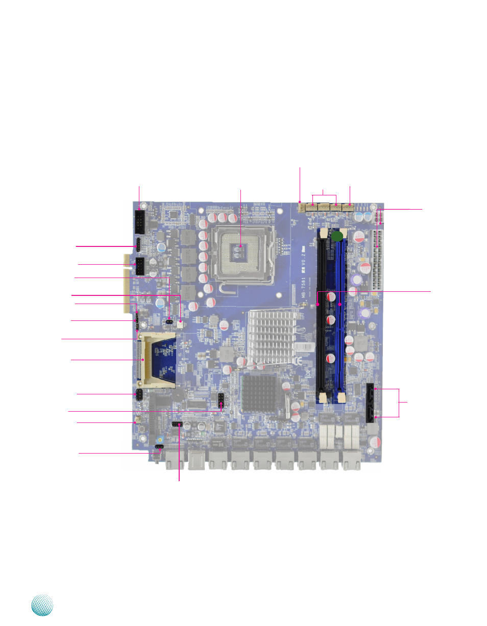
Motherboard Layout
The motherboard layout shows the connectors and
jumpers on the board. Refer to the following picture
as a reference of the pin assignments and the internal
connectors.
CF Card Connector (CF1)
CMOS (J19)
CPU Socket
SPI ROM Update Jumper
(SPI-ROM1)
Serial Cable
Connector (J13)
VGA Cable
Connector (J9)
System Power Button
Connector (CONN2)
ATX Power
Connector
USB Cable
Connector (J8)
SATA 1/2
Connec
tors (J4/J3)
Keyboard and
Mouse
Connectors (J16)
Hardware and Software
Reset Jumper (J14)
Port 80 Pin
Header (LPC1)
AT Mode Power Button
Connector (CONN1)
AT Mode Jumper (J10)
M16
Fan
Connector
CPU Fan1 to Fan 3
Connectors (FAN1/
FAN2/FAN3)
CF Card Master/Slave Selection
Jumpber (J2)
DIMM Socket
(DIMM1/DIMM2)
System Fan Connector
AT/ATX Mode Selection
Jumper (J11)
- LVC-2000 (39 pages)
- LVC-5000(N4) (42 pages)
- LVC-5550S (41 pages)
- LVC-5570 (48 pages)
- LVC-5770 (49 pages)
- FW-6432 (16 pages)
- FW-7525 (41 pages)
- FW-5330 (38 pages)
- FW-6486 (18 pages)
- FW-6436 (19 pages)
- FW-7573 (44 pages)
- FW-7568 (52 pages)
- FW-7540 (47 pages)
- FW-8759 (47 pages)
- FW-8758 (42 pages)
- FW-7610 (44 pages)
- FW-8756 (24 pages)
- FW-7575 (48 pages)
- FW-8760 (53 pages)
- FW-8877 (46 pages)
- FW-8892 (58 pages)
- FW-8893C (49 pages)
- FX-3411 (48 pages)
- FW-8894 (31 pages)
- FW-8771 (47 pages)
- RS12-38800 (64 pages)
- MR-320 (20 pages)
- FX-3210 (54 pages)
- MR-301 (16 pages)
- MR-350 (12 pages)
- MR-330A (16 pages)
- MR-730 (18 pages)
- VES-220 (19 pages)
- VES-270 (19 pages)
- VES-310 (15 pages)
- VES-310 V2 (20 pages)
- VES-500 (21 pages)
- EM-F345 (30 pages)
- VES-8X2 (16 pages)
- VES-8X6 (17 pages)
- LEC-2026 (67 pages)
- LEC-2010 (65 pages)
- LEC-2136 (20 pages)
- LEC-2050 (38 pages)