Jumper settings, Chapter 3, Motherboard information – Lanner FW-7581 User Manual
Page 12
9
Motherboard Information
Chapter 3
Network Application Platforms
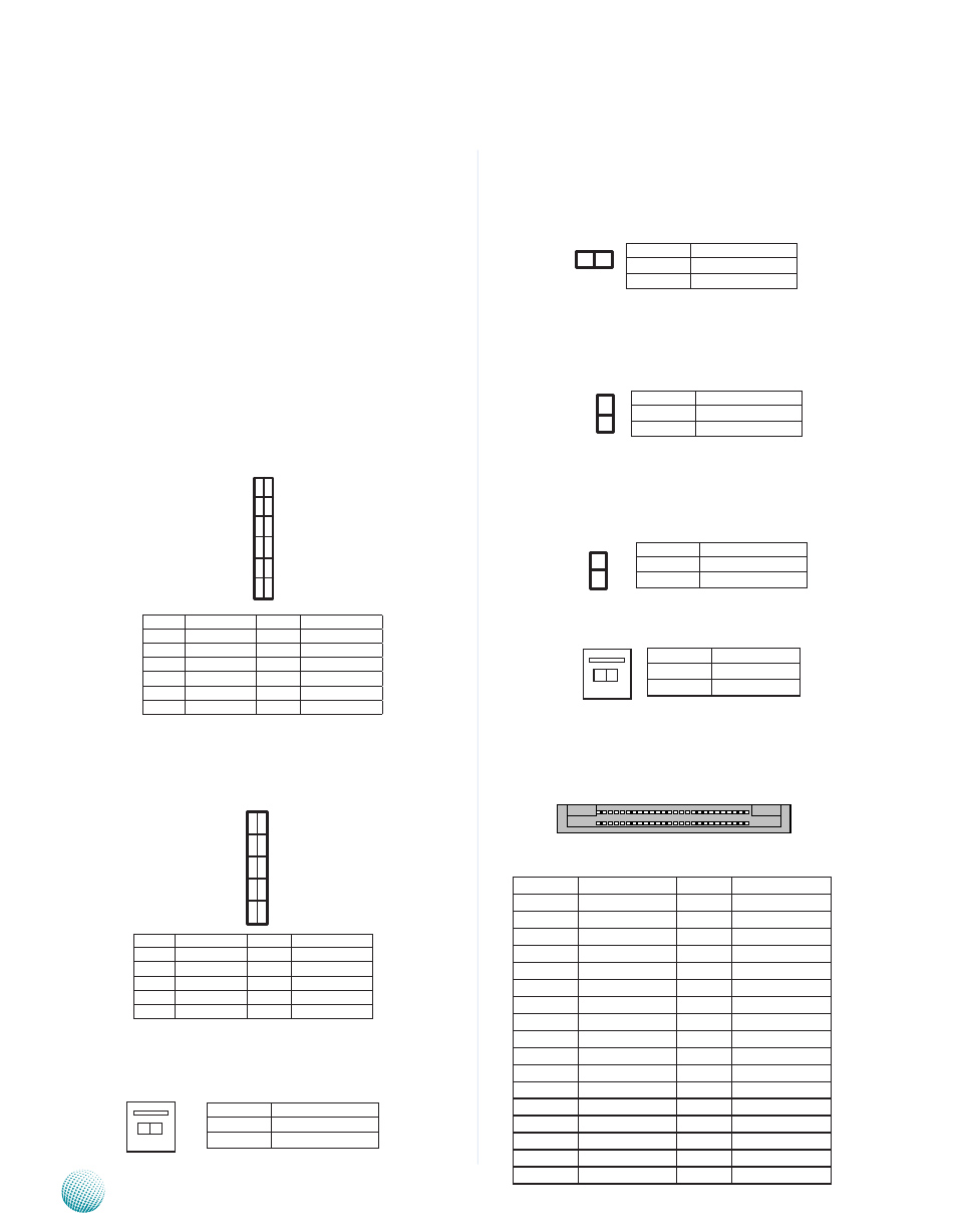
Jumper Settings
VGA Interface (J9): An 2x6 (2.0mm) header for
connecting the VGA interface cable. The VGA is provided
by the integrated 82G41 Graphics Memory Controller Hub
(GMCH) which utilizes the Intel Graphics Media Accelerator
X4500 and has the following capabilities:
Built-in smooth high-definition video playback,
•
without the need for add-in video cards or decoders.
Support of Intel Clear Video Technology, which
•
enhances the visual experience with a combination
of video-processing hardware and software
technologies.
Support of Microsoft DirectX 10, Shader Model 4.0
•
and OpenGL 2.0.
USB Connector (J8) : An 2x5 pin header for connecting
the USB module cable. It complies with USB2.0 and
support up to 480 Mbps connection speed.
AT Mode Power Button Connector (CONN1): It is for
connecting power switch in AT mode. Note that you will
need to adjust the jumpers J10, J11, and J19 altogether
below.
AT/ATX Mode Selection Jumper(J10): Jumpers J10, J11,
and J19 are used for switching power mode between AT
and ATX. Please adjust them accordingly as described in
the following jumper settings.
AT/ATX Mode Selection Jumper(J11): Jumpers J10, J11,
and J19 are used for switching power mode between AT
and ATX. Note that you have to adjust jumpers J10 and J19
accordingly.
AT/ATX Mode Selection Jumper(J19): Jumpers J10, J11,
and J19 are used for switching power mode between AT
and ATX. Note that you have to adjust jumpers J10 and J11
accordingly.
2-pin System Power Switch (CONN2): This connector is
for connecting power switch in ATX mode (CONN2).
CompactFlash Connector (CF1): It is for connecting a
Compact Flash card to be served as your system’s storage.
PIN
DESCRIPTION PIN
DESCRIPTION
1
GND
26
CD1-
2
DATA3
27
DATA11
3
DATA4
28
DATA12
4
DATA5
29
DATA13
5
DATA6
30
DATA14
6
DATA7
31
DATA15
7
CE1#
32
CE2#
8
NC
33
NC
9
GND
34
IOR#
10
NC
35
IOW#
11
NC
36
WE#
12
NC
37
READY#
13
CFVCC3
38
CFVCC3
14
NC
39
CSEL
15
NC
40
NC
16
NC
41
RESET
17
NC
42
WAIT#
1 1
9
7
5
3
1
12
10
8
6
4
2
1
3
5
7
9
2
4
6
8
10
25 1
50 26
CF1
Pin No. Pin Name
Pin No.
Pin Name
1
Red
2
GND
3
Green
4
GND
5
Blue
6
GND
7
HSYNC
8
KEY
9
VSYNC
10
GND
11
DD_DATA
12
DD_CLK
Pin No. Pin Name
Pin No.
Pin Name
1
VCC
2
VCC
3
USBD-
4
USBD-
5
USBD+
6
USBD+
7
GND
8
GND
9
GND
10
GND
2
1
Pin No.
Function
1-2
ATX mode (Default)
---
AT mode
Pin No.
Function
--
ATX mode (Default)
1-2
AT mode
2
1
Pin No.
Function
--
ATX mode (Default)
1-2
AT mode
2 1
Pin No.
Function
1
DC_ON_N
2
GND
2 1
Pin No.
Pin name
1
FP_SWIN_R
2
GND
2 1