Chapter 3: motherboard information, Block diagram, Chapter 3 – Lanner FW-7581 User Manual
Page 10: Motherboard information, Mb-7581
7
Motherboard Information
Chapter 3
Network Application Platforms
Chapter 3:
Motherboard Information
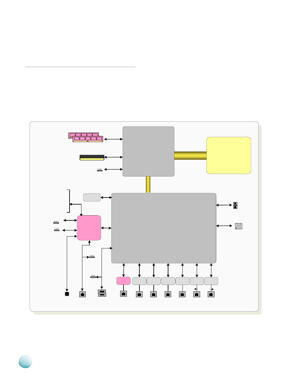
Block Diagram
The block diagram depicts the relationships among the
interfaces or modules on the motherboard. Please refer
to the following figure for your motherboard’s layout
design.
Intel
(LGA775)
Conroe
Wolfdale
Intel G41
(25W)
INTEL
ICH7/ICH7R
(~3W)
LPC
FSB
800/1066/1333MHz
6x GbE RJ-45
Connectors w/ LED
6x PCI-E x1
8.5GB/s
DDR3 1333 MHz
Non-ECC Unbuffered
1x 2.5"
HD Bay
DMI x2/x4
PC
I 1
.1
Compact Flash
2x USB
PIN header
2x USB
connectors
USB
2.0
2x
S
AT
AII
2x SATAII Ports
Du
al
Ch
an
ne
ls
Up to 4GB Maximum
PCI-E x8 Golden Finger
Intel
82574L
Intel
82574L
Winbond
83627DHG
2x Console
PIN header
LCM
KB/Mouse
GPIO
Fan Monitor
Thermal Monitor
SPI
Intel
82574L
Intel
82574L
Intel
82574L
Intel
82574L
TPM
IDE
VGA
VGA PIN Header
For REAR DB19
RJ45
console
Watchdog
Reset
Bottom
DM
9620
10/100
Mng.port
By-pass
MB-7581
10/100
MAC