Start-up, Maintenance, Valve seats – Jordan Valve Mark 37 Series – Motor Operated Control Valve User Manual
Page 2
A. DISASSEMBLY
The sliding gate seats of Jordan Valves are
precision lapped. Maintaining such tolerances is
of paramount importance for your assurance of
excellent control and tight shutoff. DO NOT use
metallic objects in removing the seats. Care in
handling is imperative.
Close the shutoff valve on each side of the control
1.
valve, and remove the valve from the line.
Note the scribes “<” on the side of the valve body
2.
and cap. Secure the body flats in a vise. Remove
the cap bolts and two nuts, and lift the cap straight
up.
Before removing, check the valve disc for a
3.
stamped arrow. This arrow points to the “<“ on the
body. (Certain disc that can be rotated 180° with-
out affecting valve stroke may not have an arrow.)
Remove the disc guide and the valve disc. Place
the valve disc on the bench with lapped surface
facing up. Protect the lapped surfaces on both
sides of the disc guide.
Clean all the parts, body, and cap with solvent.
4.
Place a piece of 4/0 polishing cloth or jewelers
cloth on a smooth, flat surface such as surface
plate, and polish the lapped seating surfaces of the
disc, plate and disc guide using a “figure 8” motion.
If the parts are scarred, do not attempt to re-lap
them, but return them to the factory for repair or
replacement. If the seats are not scarred deeply,
they can be repaired at a nominal cost.
The vertical sections of the disc guide serve as
5.
guides for the valve disc while stroking. A 0.005
feeler gauge should be used to check for clearance
between this surface and the side of the valve disc.
If the clearance is less, clean the guide surfaces in
the disc guide with a fine file.
B. REASSEMBLY
Place the plate in the body, lapped surface facing
1.
the cap. The index pin hole should be on the same
side of the body as the “<” on the body. Align the
disc pin so that it is centered in the body bore and
that it protrudes through the center slot in the valve
plate (this should be the longer of the two exten-
sions if the disc pin is cast).
Place the valve disc on the valve plate, engaging
2.
the disc pin. The arrow on the disc should point to
the index pinhole. Insert the index pin in the hole.
Place the disc guide onto the valve plate, engaging
3.
the index pin. Rotate the assembly slightly until the
slot openings in the disc are parallel to the open-
ings in the plate and perpendicular to the stem.
Stroking the valve will aide in this alignment.
Align the “>” on the cap with the “<” on the body,
4.
and place the cap over the two studs in the body.
solderless connectors or by soldering and then taping
the connections. For specific wiring instructions based
on your control range and command signal, see Supple-
mental Motor Literature supplied with your valve upon
shipment.
Start-Up
Be sure that the action of the control valve and of
1.
the controller are such as to give the desired re-
sults.
With the inlet, outlet, and bypass shutoff valves
2.
closed, and no pressure in the downstream line,
fully open the outlet shutoff valve. Slowly open the
inlet valve just enough to start flow through the
control valve. Increase flow gradually by slowly
opening the inlet shutoff valve. Do not fully open
the inlet valve until you are sure that the controller
and control valve have control of the system. Usu-
ally the handwheel on the inlet valve will turn freely
when this point is reached.
To shut off the line fluid, close the inlet shutoff
3.
valve first, then the outlet shutoff valve.
Maintenance
Caution: Make certain that there is no pressure in the
valve before loosening any fittings or joints. The fol-
lowing steps are recommended:
Close the inlet shutoff valve.
1.
Allow pressure to bleed off through downstream
2.
piping. Do not attempt to reverse the valve by
bleeding pressure from the upstream side of the
valve.
When the pressure gauges indicate that all pres-
3.
sure has been removed from the system, close the
outlet shutoff valve, and the valve may be serviced.
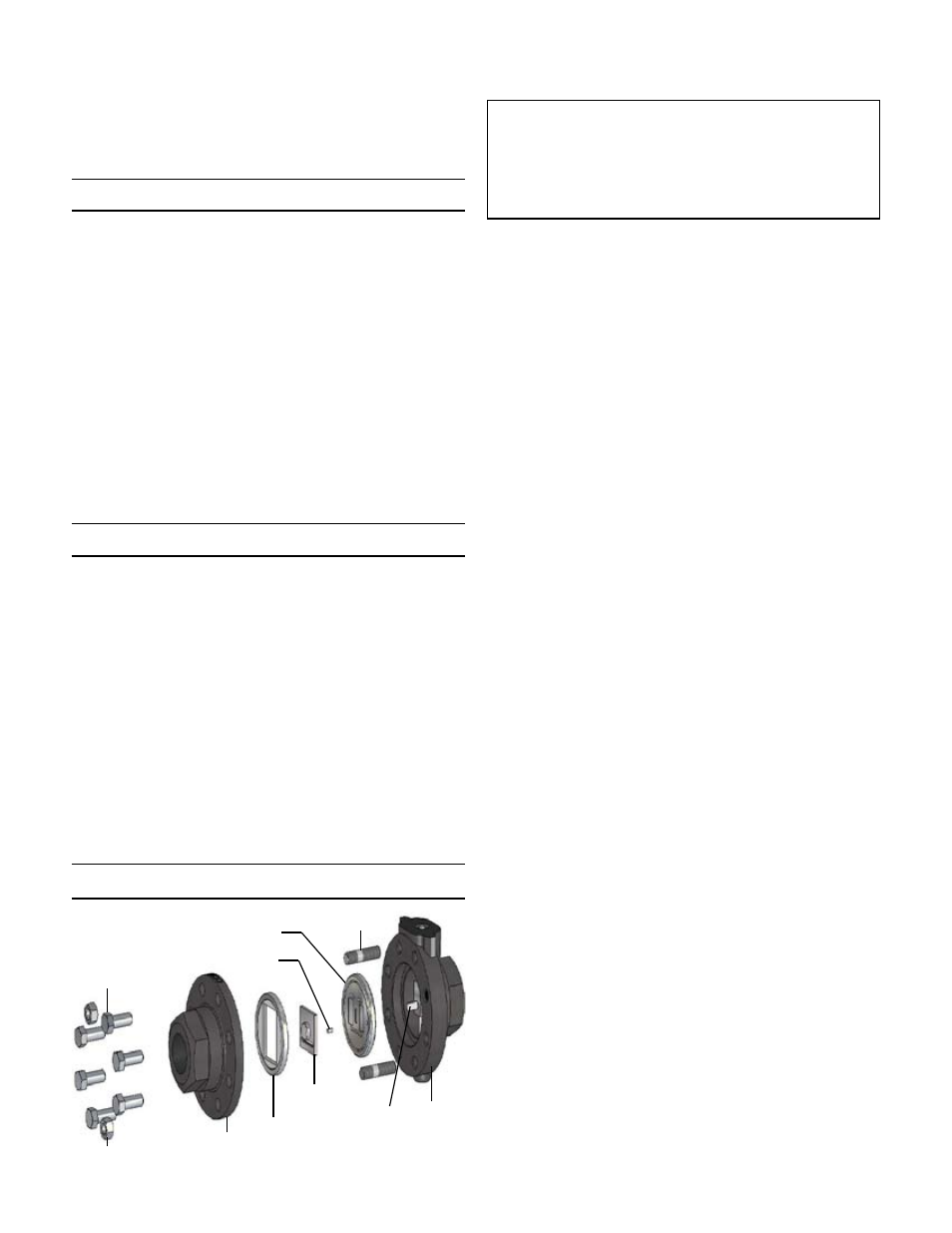
Note: refer to the drawing at the end of this docu-
ment for description and proper orientation of parts.
Valve Seats
-2-
Cap
Disc Guide
Valve Disc
Studs (2)
Body
Hex Nuts (2)
Cap Screws
Disc Pin
Index Pin
Valve Plate