Aintenance, 128pqc s – Jordan Valve Mark 128PQC Series Control Valve User Manual
Page 2
M
ark
128PQC S
erieS
C
ontrol
V
alVe
-2-
M
aIntenance
Warning:
Prior to performing any maintenance, isolate the valve from
the process pressure. Vent control input signal pressure.
Relieve the process pressure and drain process media from
both sides of valve (Figure 5, Key 27). A sudden release
of pressure or fluid can cause personal injury or property
damage.
Scheduled inspections and maintenance are vital to contin-
ued operation of all pressure control valves and systems.
Parts are subject to wear and tear, and must be replaced
as necessary, depending on the intensity of service con-
ditions. Unless the valve body requires maintenance or
replacement, it may remain in the pressure system or on the
vessel.
Replacing Packing and Trim
Follow these procedures when replacing the entire pack-
ing and trim assembly or individually replacing packing
and trim parts. Unless otherwise indicated, key num-
bers in this section reference Table 2 for parts listings
for replacement packing and trim assembly, Figure 2 for
packing and trim assembly key numbers and Figure 4
control valve assembly key numbers.
1.
Detach the control valve from all pressure, and
release pressure from valve body and actuator.
Ensure the valve is completely closed.
2.
Remove the four nuts (Key 32) from the screws
of the lower diaphragm casing. After discon-
necting the input signal tubing, remove
the actuator from the valve body, along with at-
tached trim parts.
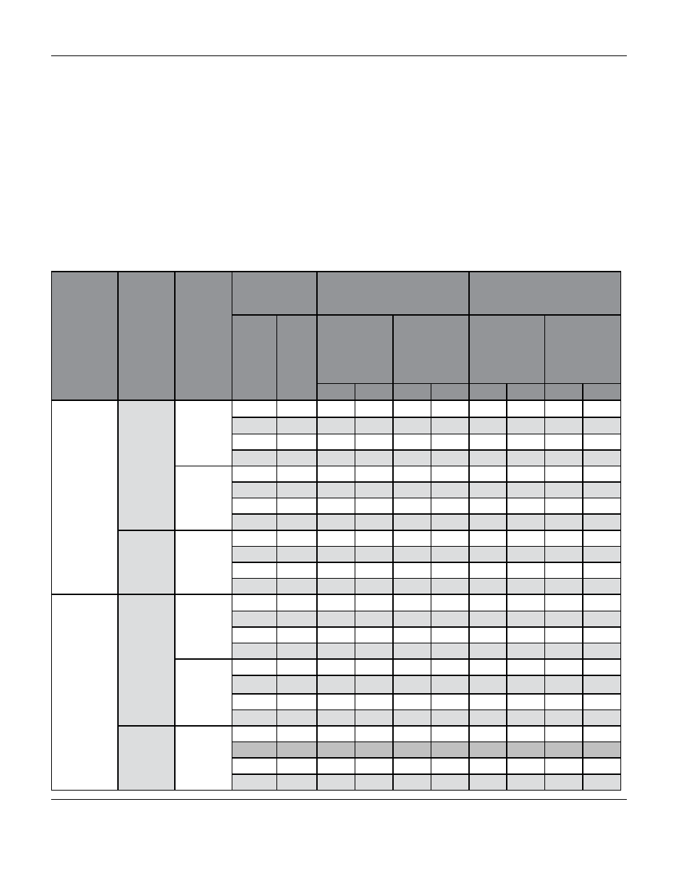
Table 1: Maximum Allowable Shutoff Pressure Drops
Seating
Actuator
Action
Flowing
Pressure
Drop
Tends
To:
Port Diameter
Cadmium Coloured Main Spring
14A8831X012
Red Main Spring 14A9077X012
ln
mm
At 20 Psig (1.4
bar) Operating
Signal
Pressure
(2 Springs
Req’d)
At 35 Psig (2.4
bar) Operating
Signal
Pressure
(4 Springs
Req’d)
At 20 Psig (1.4
bar) Operating
Signal
Pressure
(2 Springs
Req’d)
At 35 Psig (2.4
bar) Operating
Signal
Pressure
(4 Springs
Req’d)
Psi
Bar
Psi
Bar
Psi
Bar
Psi
Bar
Metal
(All Types)
Fail Close
Open
Valve
1/4
6.4
1510
104
3370
232
3880
233
3600
248
3/8
9.5
520
36
1340
92
1340
92
3120
215
1/2
12.7
220
15
690
47
700
48
1720
118
3/4
19.1
30
2.1
240
16
240
16
710
49
Close
Valve
1/4
6.4
940
65
1860
128
1370
94
2920
201
3/8
9.5
1130
78
2450
169
1540
106
3300
227
1/2
12.7
1330
92
2920
201
1710
118
3600
248
3/4
19.1
2030
140
3600
248
2320
160
3600
248
Fail
Open
Close
Valve
1/4
6.4
170
12
350
24
---
---
---
---
3/8
9.5
530
36
610
42
---
---
---
---
1/2
12.7
540
37
1150
79
---
---
---
---
3/4
19.1
1400
96
2910
200
---
---
---
---
Soft
Fail Close
Open
Valve
1/4
6.4
1000
69
1000
69
1000
69
1000
69
3/8
9.5
710
49
1000
69
1000
69
1000
69
1/2
12.7
400
28
830
57
830
57
1000
69
3/4**
19.1**
160
11
350
24
360
25
790
54
Close
Valve
1/4
6.4
940
65
1000
69
1000
69
1000
69
3/8
9.5
1000
69
1000
69
1000
69
1000
69
1/2
12.7
1000
69
1000
69
1000
69
1000
69
3/4**
19.1**
1000
69
1000
69
1000
69
1000
69
Fail
Open
Close
valve
1/4
6.4
560
39
660
45
---
---
---
---
3/8
9.5
480
33
960
66
---
---
---
---
1/2
12.7
540
37
1000
69
---
---
---
---
3/4***
19.1**
1000
69
1000
69
---
---
---
---