Arts, Rdering, Assembly continued – Jordan Valve Mark EZ Series Globe Style Control Valve User Manual
Page 8: Ez s
-8-
Assembly Continued,
7. Mount the bonnet on the valve body and
complete the assembly according to steps
10 through 15 of the Replacing Packing
procedure, omitting steps 12 and 13 if new
packing is not being installed, and being
sure to observe the note prior to step 11.
Composition seats, refer to figure 12.
Insert
the disk (key 29) in the valve plug guide (key
27). Screw the tip (key 30) into the valve
plug guide to clamp the disk in place. Using
a 3/32-inch bit, drill through the valve plug
tip using the hole in the valve plug guide as
a drilling guide. Remove any chips or burrs
and drive in a new pin (key 31).
P
arts
o
rderIng
Each valve is assigned a serial number,
which can be found on the valve body. This
same number also appears on the actuator
nameplate when the valve is shipped from
the factory as part of a control valve
assembly. Refer to the serial number when
contacting your Jordan Valve sales office for
technical
assistance.
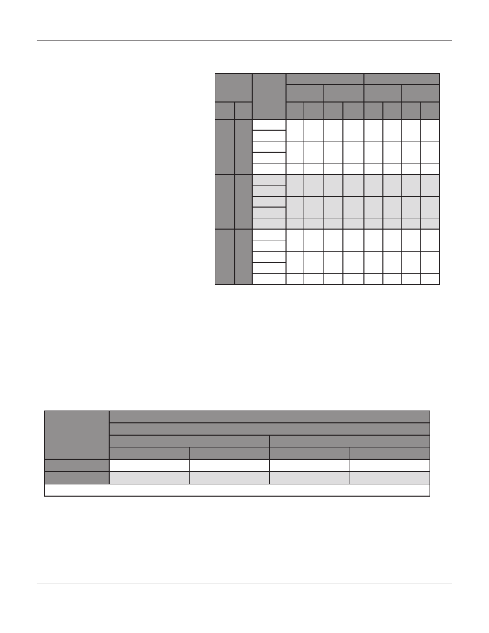
Table 2.
Recommended torques for Packing Flange Nuts (Not for
Spring Loaded Packing)
Valve
Stem
Diameter
Pressure
Rating
Graphite Type Packing
PTFE Type Packing
Minimum-
Torque
Maximum
Torque
Minimum
Torque
Maximum
torque
mm
in
Nm
Lbf
in.
Nm
Lbf
in.
Nm
Lbf
in.
Nm
Lbf
in.
9.5
3/8
CL125
3
27
5
40
1
13
2
19
CL150
CL250
4
36
6
53
2
17
3
26
CL300
CL600
6
49
8
73
3
23
4
35
12.7
1/2
CL125
5
44
8
66
2
21
4
31
CL150
CL250
7
59
10
88
3
28
5
42
CL300
CL600
9
81
14
122
4
39
7
58
19.1
3/4
CL125
11
99
17
149
5
47
8
70
CL150
CL250
15
133
23
199
7
64
11
96
CL300
CL600
21
182
31
274
10
87
15
131
Table 2.
Body to Bonnet Torque Guidelines
Valve Size
Inches
Torque
Bolt Material
SA193-B7
SA193-B8M (1)
Lb•ft
Nm
Lb•ft
Nm
1
95
129
47
64
1-1/2 or 2
71
96
33
45
1.SA-193-B8M annealed
M
ark
EZ S
EriES
G
lobE
S
tylE
C
ontrol
V
alVE