Lapping metal seats, Assembly, Ez s – Jordan Valve Mark EZ Series Globe Style Control Valve User Manual
Page 6
Lapping Metal Seats
With metal-seat constructions, seating surfaces of
the valve plug and seat ring (key 2, figure 11) can be
lapped for improved shutoff. (Deep nicks should be ma-
chined out rather than ground out.) Use a good quality
lapping compound of a mixture of 280 to 600-grit. Apply
the compound to the bottom of the valve plug.
Assemble the valve to the extent that the seat ring
retainer is in place and the bonnet is bolted to the
valve body. A simple handle can be made from a
piece of strap iron locked to the valve plug stem with
nuts. Rotate the handle alternately in each direction to
lap the seats. After lapping, remove the bonnet and
clean the seat surfaces. Completely assemble as de-
scribed in the assembly portion of the Trim Maintenance
procedure and test the valve for shutoff. Repeat the
lapping procedure if leakage is still excessive.
Assembly
The following procedure assumes that all the trim and
associated gaskets were removed from the valve body.
If these parts were not all removed, start the assem-
bly procedure at the appropriate step. Key numbers
referenced in the following steps are found in figure 11,
unless otherwise indicated.
Valves with Plain or Extension Bonnets
Perform the following steps to assemble and install
the trim.
To avoid weakening the stem that may cause failure
in service, never reuse an old stem with a new valve
plug. Using an old stem with a new plug requires
drilling a new pin hole in the stem, which will weaken
the stem. However, a used valve plug may be reused
with a new stem.
1.
For valves with metal seats,
screw the valve
stem (key 7) into the valve plug (key 2). Tighten
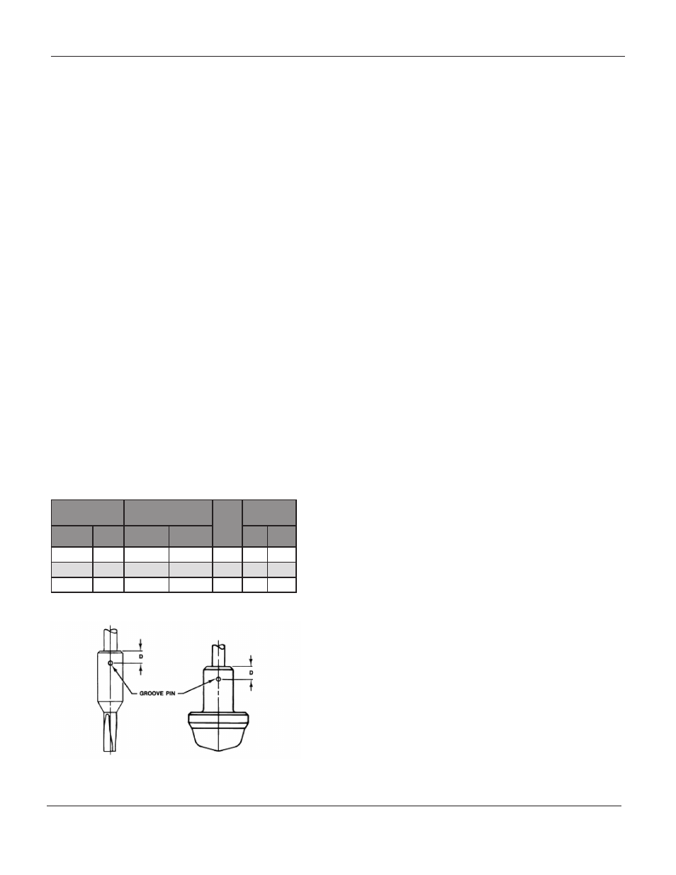
to the torque valve given in figure 9. Refer
to figure 3 to select the proper drill size. Drill
through the stem using the hole in the valve
plug as a guide. Remove any chips or burrs
and drive in a new pin (key 8) to lock the as
sembly.
2.
For valves with 1/4 and 3/8-inch ports and
composition seats,
refer to figure 12. Place the
disk (key 29) on the valve plug tip (key 30).
Place the disk retainer (key 28) over the disk,
and then thread the disk retainer onto the valve
plug guide (key 27).
To avoid failure in service for valves with 1/2 through
1-inch ports and composition seats, never reuse an
old valve plug guide with a new valve plug tip. Using
an old valve plug guide with a new plug tip requires
drilling a new pinhole in the valve plug guide, which
will weaken the guide. However, a used valve plug tip
may be reused with a new valve plug guide.
For valves with 1/2 through 1-inch ports and
composition seats,
refer to figure 12. Insert the
disk (key 29) in the valve plug guide (key 27). Screw the
tip (key 30) onto the valve plug guide to clamp the disk
in place. Using a 3/32-inch bit, drill through the valve
plug guide using the hole in the tip as a drilling guide.
Remove any chips or burrs and drive in a new pin (key
31).
Figure 9. Bolt Torque for Plug/Stem Connection and
Plug/Adaptor Connection and Pin
Replacement
-6-
Valve
Stem
Bolt Torque
Drill
Size,
Inch
D
Dimension
mm
Inch
N•m
Lbf•ft
mm Inch
9.5
3/8
40-47
25-35
3/32
16
5/8
12.7
1/2
81-115
60-85
1/8
19
3/4
19.0
3/4
237-339
175-250
3/16
25
1
M
ark
EZ S
EriES
G
lobE
S
tylE
C
ontrol
V
alVE
Table 1: Body to Bonnet Bolt Torques and Drill Size