Start up, Maintenance, Valve seats – Jordan Valve Mark 66 Series – Air Loaded Pressure Regulator User Manual
Page 2
A. Disassembly
The sliding gate seats of Jordan Valve are lapped to
light band flatness. Maintaining such tolerances is of
paramount importance for your assurance of excellent
control and tight shutoff. Do not use metallic objects in
removing the seats. Care in handling is imperative.
1. Follow procedures under maintenance to remove
the valve from line.
2. Note the scribes “<” on the side of the valve body
and cap. Secure the body flats in a vise. Remove the
cap bolts and two nuts. Lift the cap straight up.
3. Before removing, check the disc for a stamped ar-
row. This arrow points to the “<” on the body.
(Note: certain discs that can be rotated 180° without af-
fecting the stroke might not have an arrow).
Remove the disc guide by lifting straight up. Also lift
straight up on the disc. Place the disc on the bench,
lapped surface facing up. Protect the lapped surfaces on
both sides of the disc guide.
It is imperative that the disc pin assembly (disc pin,
stem and locknut is not rotated when disassembling,
cleaning or reassembling, since this will affect the
stroke adjustment of the valve.
4. Invert the body and lightly tap on the exterior to
remove the plate. Let the plate drop out into your
hand, and place it on the bench with the lapped
surface facing up.
5. Clean all of the parts, body and cap with solvent.
6. Install a shutoff valve (not a needle valve) in the
control line. Install a pressure gauge in the control
line or near the outlet of the valve to aid in setting
the valve and for checking for inlet pressure during
maintenance procedures. (There is a 1/4” tapped
opening in the lower bonnet).
Start Up
With the inlet, outlet, and bypass shutoff valves closed,
and no pressure in the downstream line:
1. Fully open the control line shutoff valve.
2. Fully open the outlet shutoff valve.
3. Slowly open the inlet valve just enough to start flow
through the valve. Observe the downstream pres-
sure gauge. Increase the downstream pressure
slowly by gradually opening the inlet valve.
4. Do not fully open the inlet valve until you are sure
that the regulator has control of the system. Usu-
ally the handwheel on the inlet valve will turn freely
when this point is reached.
5. To change the controlled pressure, adjust the load-
ing pressure supplied to the top of the diaphragm.
Maintenance
Caution: Ensure that the valve is de-pressurized before
loosening any fittings or joints. The following steps are
recommended before performing any maintenance on
the valve:
1. Close the inlet shut-off valve.
2. Allow pressure to bleed off through the downstream
piping. Do not attempt to reverse the flow through
the valve by bleeding pressure from the upstream
side of the valve.
3. When the pressure gauges indicate that all pressure
has been removed from the system, close the outlet
shut-off valve. The valve may removed from the line
and serviced.
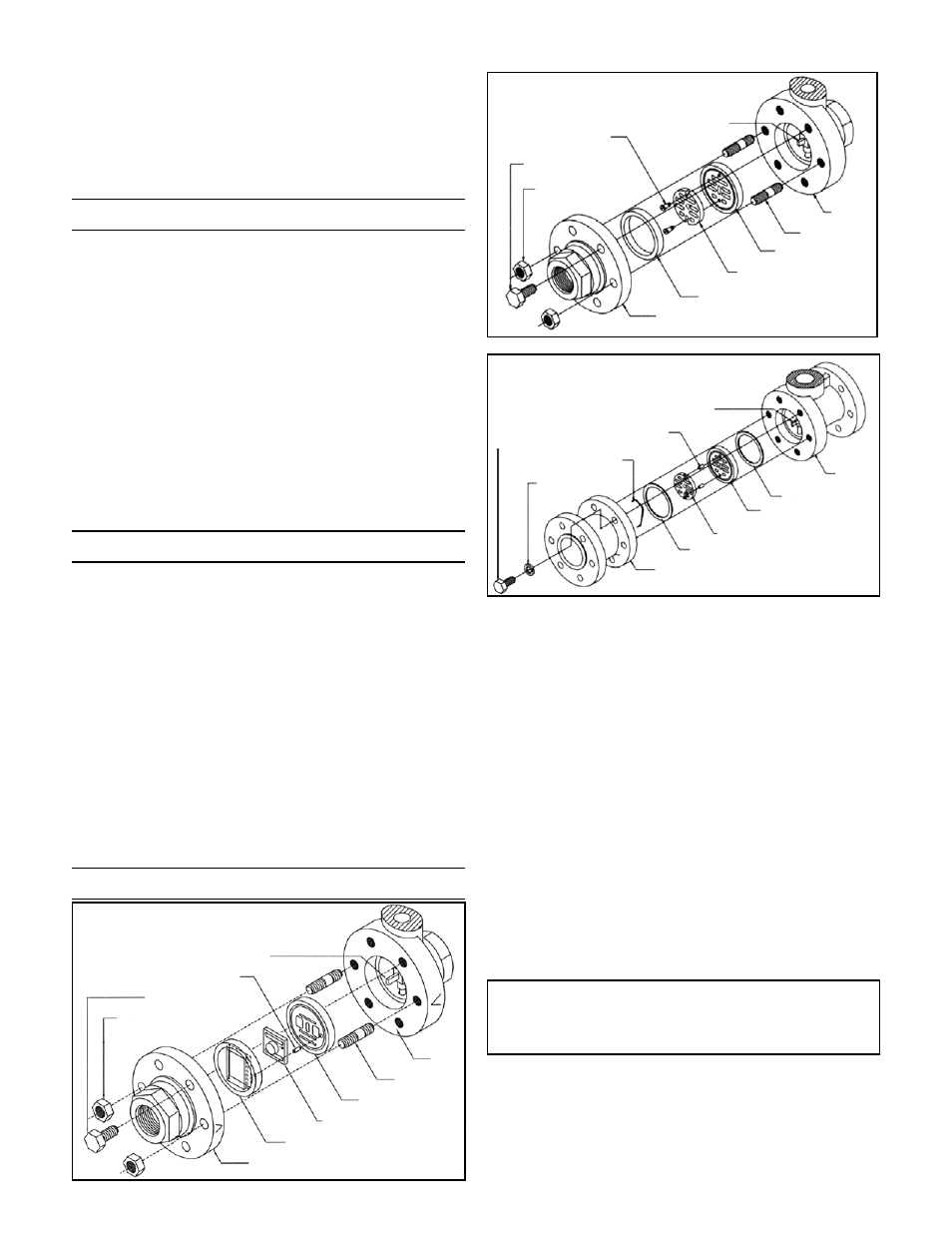
Note: Refer to the drawing at the end of this docu-
ment for description and proper orientation of parts.
Valve Seats
-2-
Disc Pin
Index Pin
Studs (2)
Body
Valve Plate
Disc Guide
Cap
Valve Disc
Cap Screws
Hex Nuts (2)
1/2” – 1-1/2”
2”
2-1/2” – 6”
Studs (2)
Body
Disc Pin
Plate
Disc
Pressure Ring
Cap
Body Bolts
Guide Screws (2)
Stud Nuts (2)
Disc Pin
Body
Gasket: Plate-Body
Plate
Disc
Gasket: Cap-Plate
Cap
Disc Guide (2)
Disc Spring
Lockwasher
Body Bolts