Figure 7, Inside the enclosure as shown in – Yaskawa Modbus TCP/IP SI-EM3D User Manual
Page 20
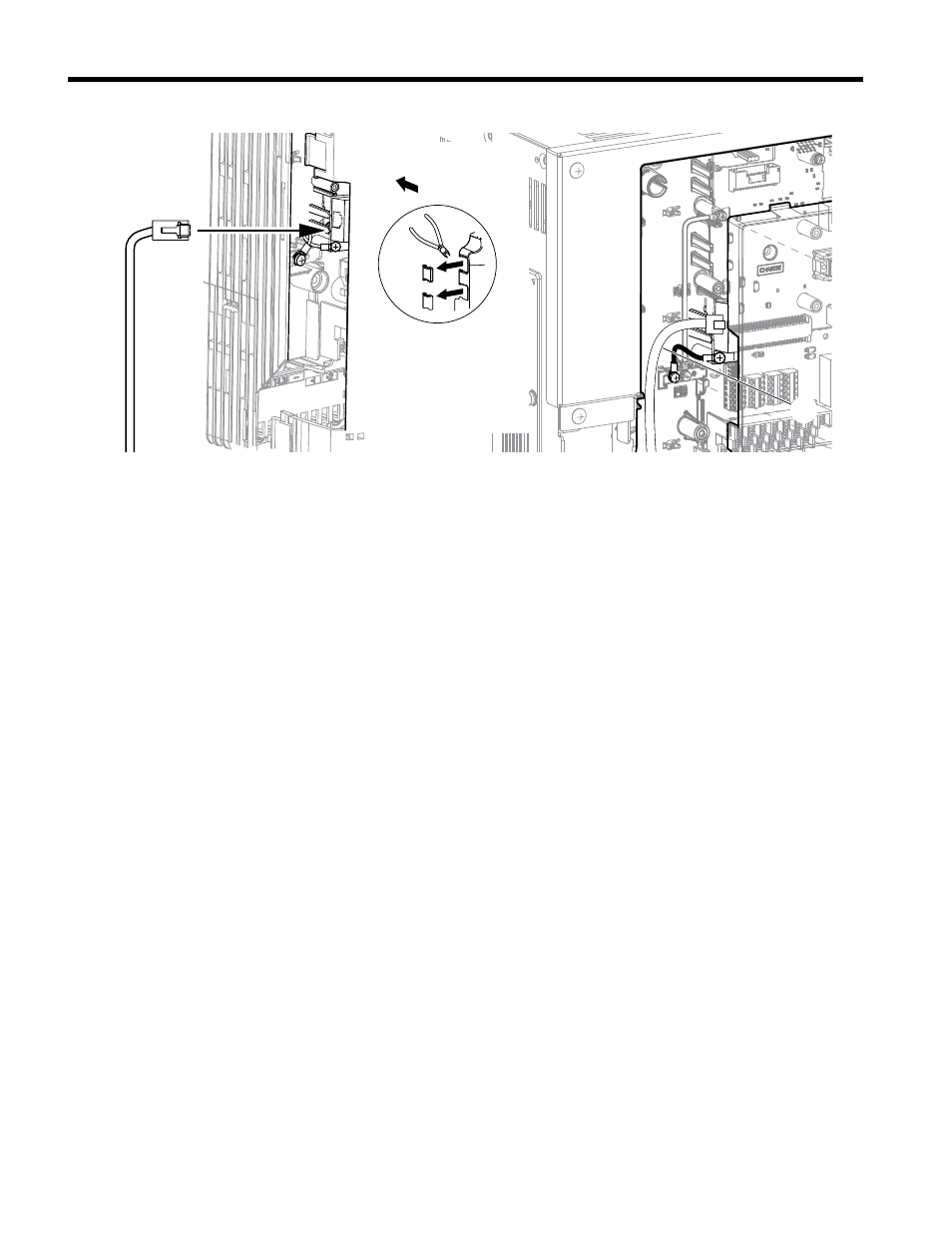
A
B
A – Route wires through the
openings provided on the
left side of the front
cover.
<1>
B – Use the open space
provided inside the drive
to route option wiring.
Figure 7 Wire Routing Examples
<1> The drive will not meet NEMA Type 1 requirements if wiring is exposed outside the enclosure.
6.
Connect the communication cable to the option modular connector (CN1) port 1.
To connect the option to a network, firmly connect RJ45 8-pin shielded twisted pair
Cat5e cable(s) into the modular connector ports (see
Communication Cable Specifications
Only use cable recommended for Modbus TCP/IP. Using a cable not specifically
recommended may cause the option or drive to malfunction.
The dual RJ45 network ports on the option board act as a switch to allow for flexibility
in cabling topology. For example, a traditional star network topology may be employed
by using a single port on the option board. Alternatively, a daisy-chained approach
may be employed by using both RJ45 ports. The daisy-chained approach reduces
the requirements of central switch ports. A ring topology is also possible. When
implementing a ring topology, Rapid Spanning Tree Protocol (RSTP) must be enabled
to function correctly.
5 Installation Procedure
20
YASKAWA TOEP YAICOM 18A 1000-Series Option Dual-Port Modbus TCP/IP SI-EM3D Installation Manual