Yaskawa MP900 User Manual
Page 2
MP920 QRG Rev1.5
S
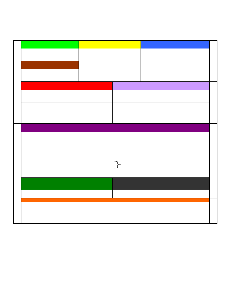
(Global)
SW0000-1023
C
(Global)
CW00000-04095
M
(Global)
MW00000-32767
System information and status (read only)
Constant, Read only registers.
General Multi-Purpose read/write registers
Example: Flicker relays, Calendar,
*Function Block RDA: MW00000-03999
Scan time setting, error codes, ect.
Axis#1: MW100-199, Axis#2: MW200-299…
Fixed Parameters
(for each axis)
Example:
User Free: MW04000-32767
Written to in Module Configuration
Mechanical system specifications
Convention:
Define axis units, motor specs.
(pulley ratios, encoder counts per load rev)
Axis#1:MW1000-1999, Axis#2:MW2000-2999
Cannot be written by ladder
Reference: RDA Spreadsheet
Changes usually require power cycle
Reference:
* If using motion function blocks.
I (Input)
IW0000-FFFF
"Motion Monitoring"
O (Output)
OW0000-FFFF
"Motion Setting"
general purpose & motion data (Read only by application program)
general purpose &motion data (Read/Write by application program)
Physical Inputs: IW0000-7FFF
Physical Outputs: OW0000-7FFF
Convention:
IW0000-0100 for Local IO modules
Convention:
OW0000-0100 for Local IO modules
IW0100+ for M-LINK Network I/O
OW0100+ for SVB and M-LINK I/O
Axis (Motion) Input: IWC000-FFFF (for axis #1)
Axis (Motion) Output: OWC000-FFFF (for axis #1)
"motion monitoring"
Offset
40h
per axis
"motion setting"
Offset
40h
per axis
400h
per module/circuit
400h
per module/circuit
Example: IBC000 0 = axis#1 controller ready
Example:
OBC000 0 = turn axis#1 servo on
Reference:
Motion Module User Man 6.2.2
Reference:
Motion Module User Man 6.2.3
D (Local Registers)*
DW00000-16383
Used as general purpose read/write in the defined Drawing only.
Suggested
Bits: DW00000-00008
(DB000000~DB00008F)
Convention:
One-Shot
DW00009
(DB000090~DB00009F)
Word Operations:
DW00010-00025
(These can be 16-bit integers, 32-bit integers, or 32-bit F
Accumulators:
DW00026
(16-bit Integer accumulator)
DW00027
(16-bit Logic [Hexadecimal] Accumulator)
DL00028
(32-bit Long Accumulator)
DF00030
(32-bit Floating point Accumulator)
Long
DW00032-00089
Float
DW00100-00256
*Default is 32 D-registers per drawing. R-click drawing in File Manager - increase to 256 when using Function Blocks.
Reference:
#
("Sharps")
#W00000-16383
Module Configuration
Drawings:
H, L, A, I
H (High Scan)
Use for all code that runs motion related functions. 2ms is usually good.
L (Low Scan)
Use for code that runs HMI, or user operated switches, lights, etc. 20ms is usually good
A (Startup)
Use for drawings that should automatically run once at controller power up.
S (System)
MP940 only - rarely used. Scan as fast as 250us for short drawings.
I (Interrupt)
Use to run a special interrupt routine after receiving a local input defined as a dedicated "Interrupt."
MP920 Memory Map
Regi
st
er M
emory
P
ro
g
ram Memo
ry
D
E
C
I
M
A
L
H
E
X
A
D
E
C
I
M
A
L
If local registers are increased as mentioned below.
Data that end user can change without needing to
access the program.
D
E
C
I
M
A
L
Local Constants. General purpose, read-only by the specifed Drawing they
are defined in.
Set up via a table in the "properties" dialog box for each
drawing. Rarely Used
Each hardware module on the rack has several configuration files. This data is
stored in program memory.
New project requires setting Module Configuration first. Select
from File Manager under Definition Folder"
Page 2 of 15