Yaskawa G7 Drive User Manual
Page 26
Date: 03/31/09, Rev: 09-03
Page 26 of 30
TM.G7SW.064
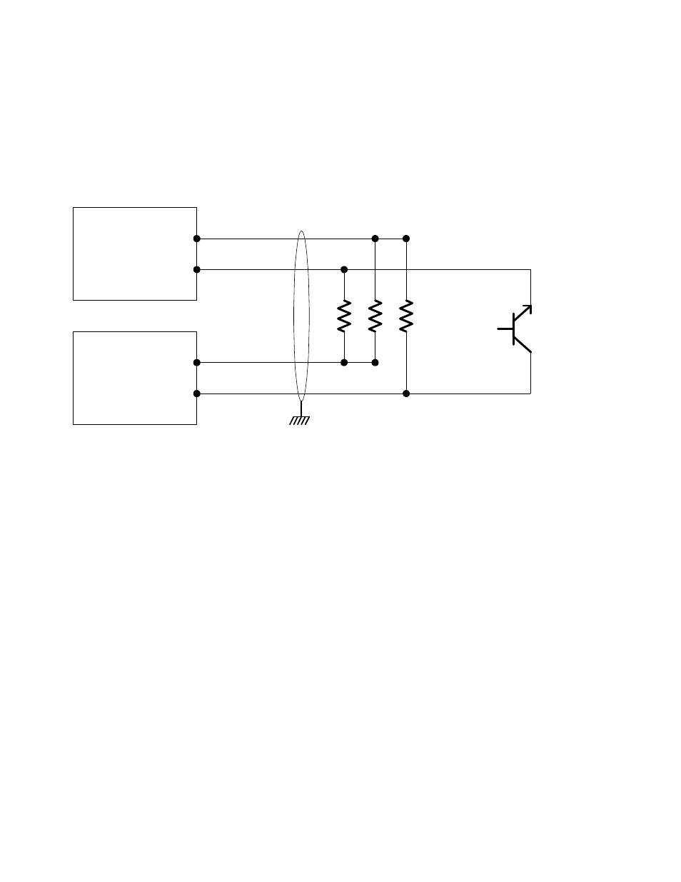
Figure 6 below shows an example of how a +12VDC current sinking (open collector NPN) sensor can be
used to trigger the marker pulse input (alignment input) of the encoder feedback card. An external power
supply may be required. For best noise immunity, locate the resistor network at the switch, not at the
encoder feedback card. Please note that the switch must be able to handle at least 22mA of current draw.
For exact application wiring, consult Yaskawa Application Engineering with the exact sensor specifications.
560 Ohm
1/2 Watt
Each
External
Alignment
Sensor
+12VDC Supply
OV Common
Z+ Marker Pulse Input
Z- Marker Pulse Input
Power Supply
Encoder Feedback Card
+
-
Twisted Pair
Twisted Pair
Use 4-wire cable with 2 twisted
pairs and 1 overall shield.
Figure 6: Wiring Example of External Alignment Sensor