Position error, Position p out, Position i out – Yaskawa G7 Drive User Manual
Page 15: Position pi out
Date: 03/31/09, Rev: 09-03
Page 15 of 30
TM.G7SW.064
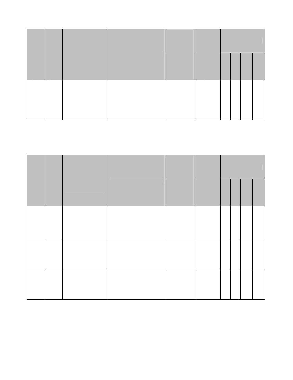
4.2 Monitors (U1-XX) (continued)
Control Mode *1
Monitor Num
ber
Modbu
s Add
ress
Monitor Name
Digital Operator
Display
Description
Scaling for
Multi-
function
Analog
Output
Terminals
FM and AM
(H4-01, H4-
04)
Unit
V/f
V/f w/ P
G
Open Lo
op
Vector 1, 2
Flu
x
Vector
U1-96 726H
Position Error
Position Error
Displays the position
error between the
master and follower
encoders in quadrature
follower encoder counts.
Note: ELS modes only.
100% =
Maximum
Output
Frequency
(E1-04)
1
Count
*2
– – – Q
*1: Access Level (A1-01): Q = “Quick Start”, A = “Advanced”, F = “Factory”, – = Not Available.
*2: Unit is dependent on the setting of the Position Units Selection (P1-10). When the position error is greater
than the maximum value that can be displayed, the digital operator will flash “OVER” in place of the U1-96 data.
When reading by network communication (register 726H), the unit is fixed at quadrature encoder counts.
4.2 Monitors (U1-XX) (continued)
Control Mode *1
Monitor Num
ber
Modbu
s Add
ress
Monitor Name
Digital Operator
Display
Description
Scaling for
Multi-
function
Analog
Output
Terminals
FM and AM
(H4-01, H4-
04)
Unit
V/f
V/f w/ P
G
Open Lo
op
Vector 1, 2
Flu
x
Vector
U1-97 727H
Position Regulator
P Output
Position P Out
Displays the
proportional gain
contribution of the
position PI regulator.
Note: ELS modes only.
100% =
Maximum
Output
Frequency
(E1-04)
0.01% – – – Q
U1-98 728H
Position Regulator
I Output
Position I Out
Displays the output of
the integrator of the
position PI regulator.
Note: ELS modes only.
100% =
Maximum
Output
Frequency
(E1-04)
0.01% – – – Q
U1-99 729H
Position Regulator
PI Output
Position PI Out
Displays the output of
the position PI regulator.
Note: ELS modes only.
100% =
Maximum
Output
Frequency
(E1-04)
0.01% – – – Q
*1: Access Level (A1-01): Q = “Quick Start”, A = “Advanced”, F = “Factory”, – = Not Available.