Yaskawa 2Y25-0423.pdf User Manual
Page 13
Rel. 09/15/2000 Page 13 of 13 Doc. No. 02Y00025-0423
Part 3: Variable Ratio Using A Potentiometer & The PG-W2 card
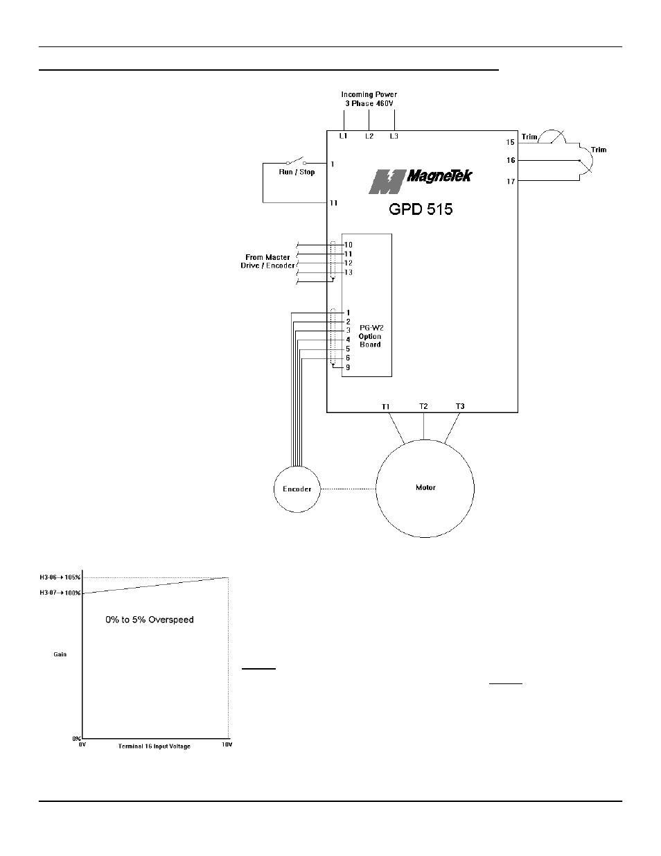
Sometimes an application will
call for a variable ratio or
“draw” while using the PG-W2
card. For example: A follower
drive needs to have an exact
speed match plus an adjustable
0 - 5% overspeed.
Parameters P1-01 & P1-02
should be calculated as
described in Part 2 of this
document. Parameter P1-03
should be left at 0.0%.
An 0 - 10V analog signal,
brought in on terminal 16, will
be scaled to represent a 0 - 5%
overspeed. This is
accomplished using the FGAIN
function, and the analog input
bias and gain functions.
The schematic on the left
shows the correct wiring for the
analog input (terminal 16) using
a potentiometer.
Parameter number H3-05
needs to be set to a “1” which
sets terminal 16 to the FGAIN
function.
Parameter numbers H3-06 & H3-07 (terminal 16 gain & bias)
need to be adjusted so that 0V on terminal 16 results in 100%
gain (1 : 1) and 10V on terminal 16 results in 105% gain (1 : 1.05).
In order to set this up, parameter H3-06 needs to be set to the
maximum amount of draw required plus 100% (5% + 100% =
105%). Parameter H3-07 needs to be set to the minimum amount
of draw required plus 100% (0% + 100% = 100%).