Yaskawa MP940-MW+ User Manual
Page 9
TECHNICAL NOTE
MOTION PRODUCT AND ENGINEERING GROUP
Yaskawa Electric America - 2121 Norman Drive South – Waukegan IL 60085
(800) YASKAWA - Fax (847) 887-7280
5/22/2003
9 of 34
eng/PubNumber/MCD
If a fault has occurred block (28) will direct execution to the fault recovery section,
otherwise block (9) is executed. Block (9) clears all of the outputs that may have inadvertently
left on. The Disable handler and the fault recovery routine both make use of Block (20). It is
simply a timer that ensures everything has settled down before attempting a restart. After block
(20) execution continues back to block (3).
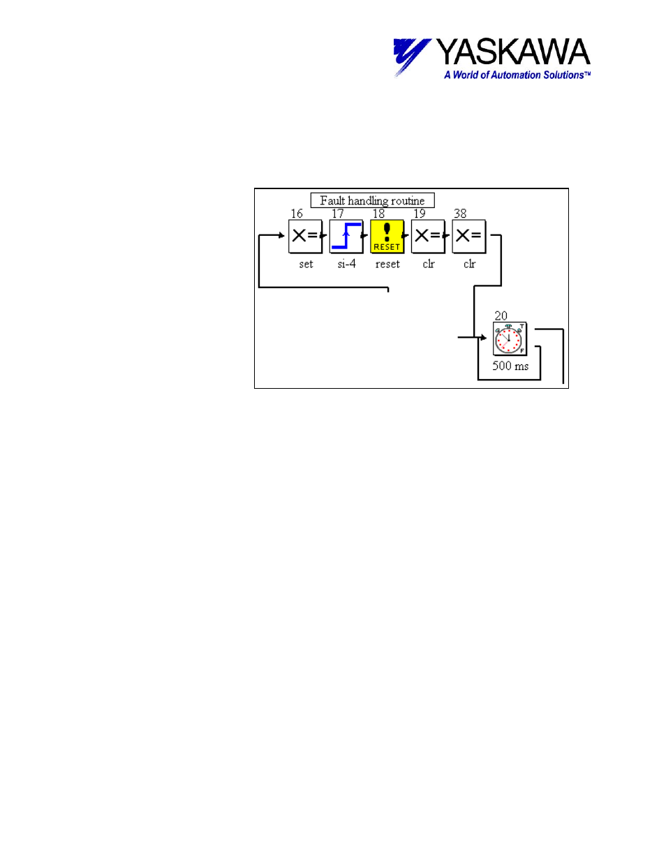
Fault Recovery
Once it has been
determined that a fault
occurred and the appropriate
blocks have executed, the
program ends up in the fault
recovery section. Block (16)
sets an output to indicate that
a fault has occurred (in the
case of the demo box, it
actually sets all eight outputs).
Input block (17) waits to see
the rising edge transition of
SGDH input SI-4
(coincidently, the Servo Alarm
Reset input when the
ServoPack is used alone).
Reset fault block (18) is a
special block that will reset
any ServoPack alarm that does not require a power cycle to reset. Lastly, Set Variable blocks 19
and 38 clear the alarm output and take care of clearing all of the internal error bits. Block (20)
was discussed above in the Disable Handler section. Conveniently, the blocks in the fault
detection section latch the fault type so the operator can tell what type of fault occurred prior to
resetting it. For example if the user variable ‘ErrorCPU’ = 1, then user will know that a MP-940
CPU error occurred. The error code is trapped in another user variable, ‘ErrorCPUCodeTrap.’
Be sure to check these prior to activating the alarm reset, as the bit indications are cleared during
an alarm reset sequence.