2 connecting the cables for the supply voltage, Connecting the cables for the supply voltage – SMA External Supply Voltage 230 V User Manual
Page 27
Procedure:
1. Disconnect the inverter on the DC side (see inverter manual).
2. Disconnect the SMA String-Monitor (see SMA String-Monitor manual).
3. Disassemble the lower protective cover of the SMA String-Monitor (see SMA String-Monitor
manual).
4. Push the connectors of the power supply assembly onto the connectors of the electronic
assembly in the SMA String-Monitor.
5. Screw the spacer bolts supplied in the scope of delivery through the holes of the power supply
assembly onto the mounting pins. As a result, the power supply assembly is fused.
6. Connect the cables for the supply voltage (see Section 4.4.2, page 27).
4.4.2
Connecting the Cables for the Supply Voltage
Requirements:
☐ The SMA String-Monitor must be disconnected (see SMA String-Monitor manual).
☐ The inverter must be disconnected on the DC side (see inverter manual).
☐ The power supply assembly must be installed (see Section 4.4.1, page 26).
Cable requirements:
☐ Conductor cross-section: 1.5 mm
2
to 2.5 mm
2
☐ Recommended cable type: NYY-O
☐ If large distances and small cable cross-sections are involved, take the voltage drop into
account.
Procedure:
1. Remove the sealing plugs from the corresponding enclosure openings (see Section 4.2, page 24
2. Lead the cables for the supply voltages through the enclosure openings into the SMA String-
Monitor.
3. Dismantle the cables by 80 mm.
4. Strip off the insulation of each conductor by 12 mm. Make sure that no pieces of cable are
dropped into the SMA String-Monitor.
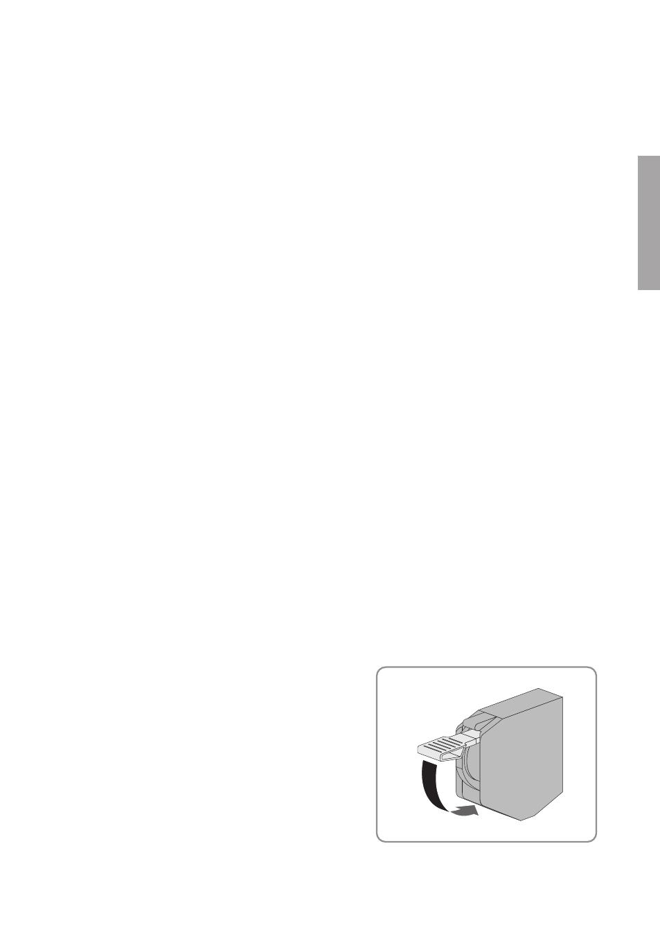
5. Connect the cable for incoming supply voltage
to terminals X22:2,3. To do this, insert the cable
into the terminal and close the locking lever of
the terminal.
4 Installation
SMA Solar Technology AG
Installation Manual
27
SSMU-AUX-PB/OVP-IA-xx-10
ENGLISH