6 commissioning, Commissioning, Connecting the meteo station to the – SMA METEO STATION Installation User Manual
Page 21: Rs485 communication bus
SMA America, LLC
6 Commissioning
Installation Manual
MeteoStation-eng-IA-IUS122210
21
6 Commissioning
6.1 Terminal Assignment of the Pre-harnessed Connection Cable
Insulated conductors 1 to 4 are already connected to the connecting terminal plate upon delivery.
The terminating resistor is connected between insulated conductors 3 and 4. Pins 5 and 6 must be
connected to the two insulated conductors of the module temperature sensor, in any order.
6.2 Connecting the Meteo Station to the RS485 Communication Bus
Requirement:
☐ The RS485 cable must be connected to the RS485 bus node (see manual of the RS485 bus node).
☐ Note the pre-harnessed termination of the Meteo Station by means of the terminator
(for details of the layout of the RS485-communication bus, see the technical description
"RS485 Cabling Plan").
1. Strip 8 in. (200 mm) of the cable sheath off the RS485 cable.
2. Shorten the cable shield to
1
⁄
2
in. (15 mm).
3. Trim the unneeded insulated conductors back as far as the cable sheath (for terminal assignment
and wiring, see the technical description "RS485 Cabling Plan").
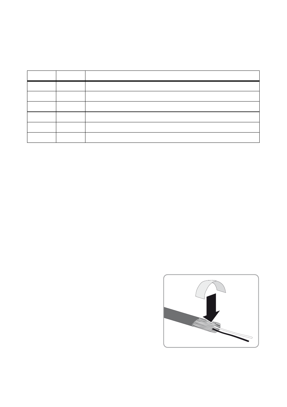
4. Pull back the cable shield and cover with conductive
adhesive foil.
5. Connect the RS485 cable to the shield connection terminal of the connection cable, making
sure that the conductive adhesive foil has electrical contact to the shield connection terminal.
Pin no.
Color
Signal designation
1
white
Ground supply voltage (GND)
2
brown
Positive supply voltage (+12 V)
3
green
RS485 (D + )
4
yellow
RS485 (D − )
5
gray
Module temperature sensor
6
pink
Module temperature sensor