2 assembling the dc connectors, Assembling the dc connectors – SMA SB 1.5-1VL-40 User Manual
Page 29
6.5.2
Assembling the DC Connectors
For connection to the inverter, all PV module connection cables must be fitted with the DC
connectors provided. Assemble the DC connectors as described in the following. Be sure to observe
the correct polarity. The DC connectors are marked with the symbols "+" and "−".
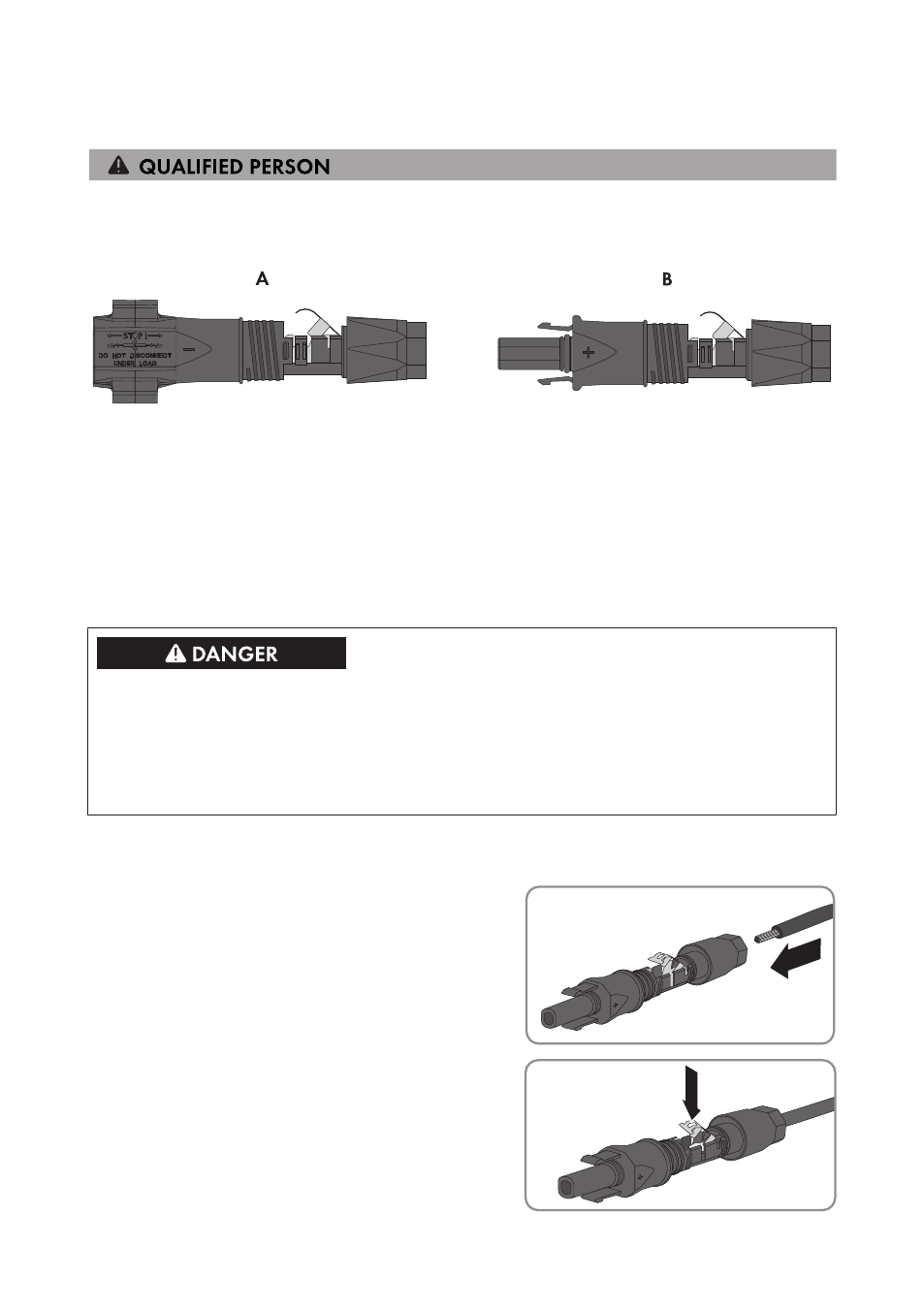
Figure 7: Negative (A) and positive (B) DC connectors
Cable requirements:
☐ Cable type: PV1-F, UL-ZKLA, USE2
☐ External diameter: 5 mm to 8 mm
☐ Conductor cross-section: 2.5 mm² to 6 mm²
☐ Qty single wires: minimum 7
☐ Nominal voltage: minimum 1,000 V
Danger to life due to high voltages on DC conductors
When exposed to sunlight, the PV array generates dangerous DC voltage which is present in the
DC conductors. Touching the DC conductors can lead to lethal electric shocks.
• Cover the PV modules.
• Do not touch the DC conductors.
Procedure:
1. Strip 12 mm of the cable insulation.
2. Insert the stripped cable into the DC connector
up to the stop. When doing so, ensure that the
stripped cable and the DC connector are of the
same polarity.
+
3. Press the clamping bracket down until it audibly
snaps into place.
+
6 Electrical Connection
SMA Solar Technology AG
Operating Manual
29
SB15-25-BE-en-10