2 mounting the inverter, Mounting the inverter – SMA SB 1.5-1VL-40 User Manual
Page 18
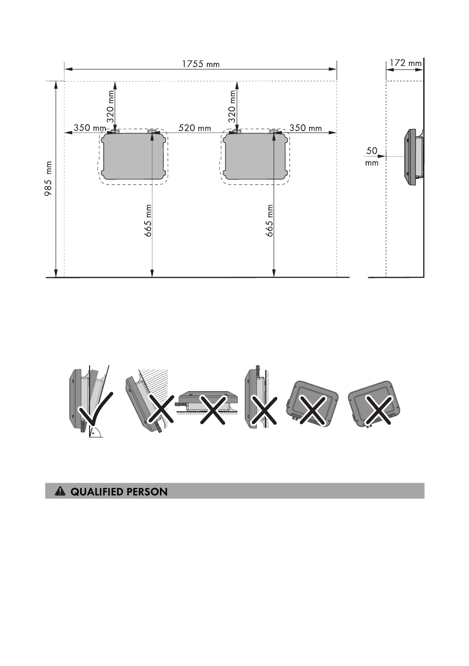
Figure 4: Recommended clearances
Permitted and prohibited mounting positions:
☐ The inverter must only be mounted in one of the permitted positions. This will ensure that no
moisture can penetrate the inverter.
☐ The inverter should be mounted in such a way that LED signals can be read without difficulty.
15°
Figure 5: Permitted and prohibited mounting positions:
5.2
Mounting the Inverter
Additionally required mounting material (not included in the scope of delivery):
☐ Two stainless steel hexagon head wood screws (AF 10, diameter 6 mm), screw length must be
suitable for the support surface and the weight of the inverter (fastening bracket thickness:
4 mm)
☐ If necessary, two screw anchors suitable for the support surface and the screws
5 Mounting
SMA Solar Technology AG
Operating Manual
SB15-25-BE-en-10
18