Diagram e – ShoreLand'r LUXR2314SW V.2 User Manual
Page 9
Midwest Industries, Inc.
Ida Grove, IA 51445
800.859.3028
www.shorelandr.com
0003809
Page 9
06/05/07
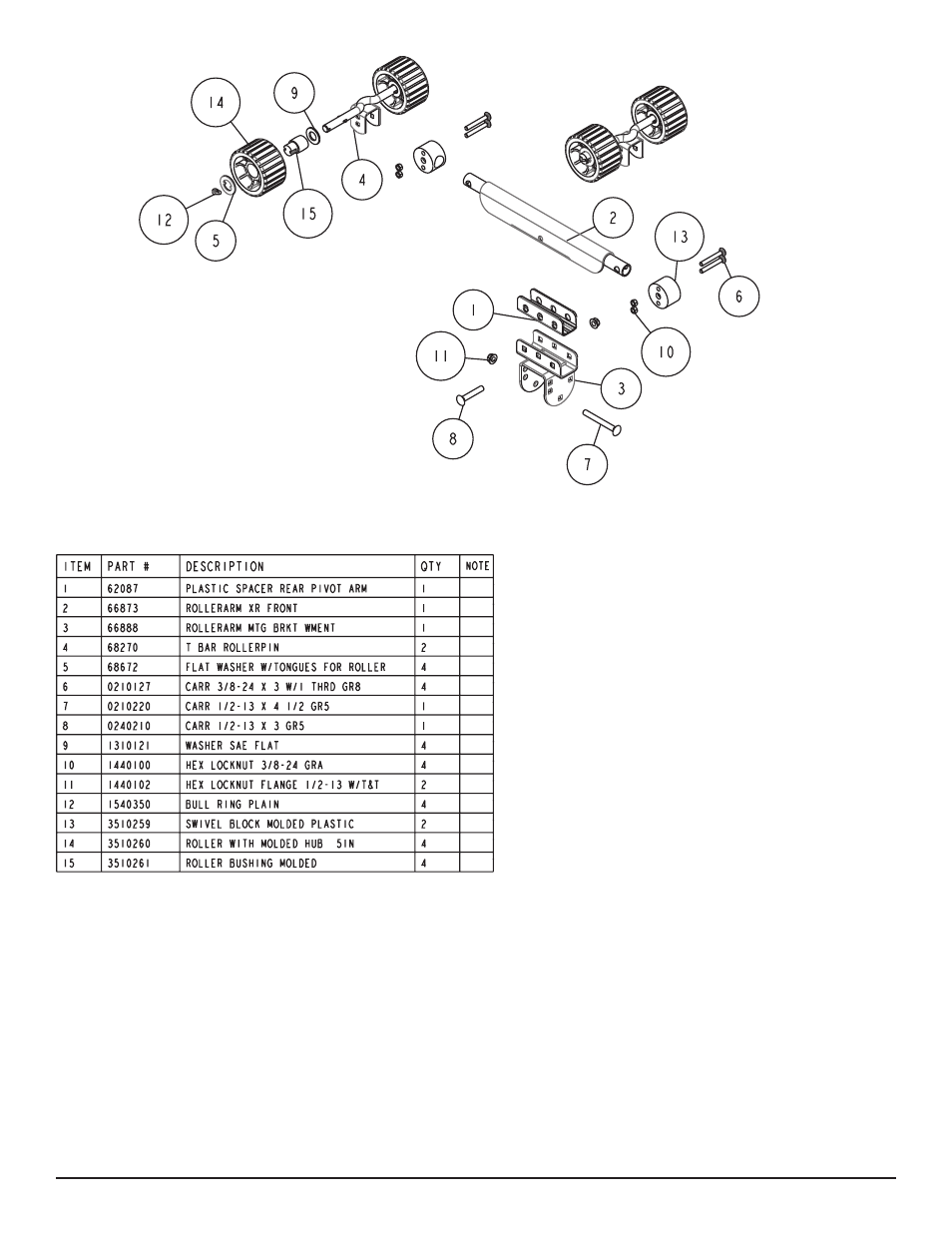
ITEM
PART #
DESCRIPTION
QTY
NOTE
1
62087
PLASTIC SPACER REAR PIVOT ARM
1
2
66873
ROLLERARM XR FRONT
1
3
66888
ROLLERARM MTG BRKT WMENT
1
4
68270
T BAR ROLLERPIN
2
5
68672
FLAT WASHER W/TONGUES FOR ROLLER
4
6
0210127
CARR 3/8-24 X 3 W/1 THRD GR8
4
7
0210220
CARR 1/2-13 X 4 1/2 GR5
1
8
0240210
CARR 1/2-13 X 3 GR5
1
9
1310121
WASHER SAE FLAT
4
10
1440100
HEX LOCKNUT 3/8-24 GRA
4
11
1440102
HEX LOCKNUT FLANGE 1/2-13 W/T&T
2
12
1540350
BULL RING PLAIN
4
13
3510259
SWIVEL BLOCK MOLDED PLASTIC
2
14
3510260
ROLLER WITH MOLDED HUB 5IN
4
15
3510261
ROLLER BUSHING MOLDED
4
1
2
3
4
5
6
7
8
9
10
11
12
13
14
15
XR SERIES
The XR-series rear roller rack is installed by placing the roller arm
assembly mounting channel over the rear cross member and se-
curing in place with a ½” x 4 ½” hex bolt and lock nut.
(See Detail
E). Note that it should be left loose until the boat is placed on the
trailer. Repeat on the other roller arm assembly. Once the proper
location is determined, it may be tightened.
Diagram E