Luxr2314sw (all colors) specifications – ShoreLand'r LUXR2314SW V.2 User Manual
Page 3
Midwest Industries, Inc.
Ida Grove, IA 51445
800.859.3028
www.shorelandr.com
0003809
Page 3
06/05/07
ShoreLand’r offers their product line in either galvanized or paint-
ed finish. When ordering parts it is important that you specify the
finish or color you have on your product. The five (5) digit number
along with a two (2) digit space _ _, note the parts which can be
purchased with various finishes. When ordering these items use
the five (5) digit number along with a two (2) digit suffix for the
proper finish.
01.........White
03.........Black
14 ......... Blue
22 ......... Red
24 ......... Majestic Red
39 ......... Galvanized w/Silver Plastic Components
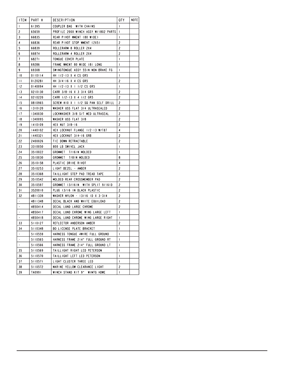
ITEM
PART #
DESCRIPTION
QTY
NOTE
1
61395
COUPLER BAG WITH CHAINS
1
2
65659
PROFILE 2000 WINCH ASSY W/1802 PARTS
1
3
66835
REAR PIVOT WMENT (80 WIDE)
1
4
66836
REAR PIVOT STOP WMENT (2X5)
2
5
66839
ROLLERARM 8 ROLLER 2X4
2
6
66874
ROLLERARM 4 ROLLER 2X4
2
7
68271
TONGUE COVER PLATE
1
8
69286
FRAME WMENT 80 WIDE 181 LONG
1
9
69308
SWINGTONGUE ASSY 55IN NON BRAKE FG
1
10
0110114
HH 1/2-13 X 4 CS GR5
1
11
0120281
HH 3/4-16 X 4 CS GR5
2
12
0140094
HH 1/2-13 X 1 1/2 CS GR5
1
13
0210130
CARR 3/8-16 X 3 3/4 GR5
2
14
0210220
CARR 1/2-13 X 4 1/2 GR5
2
15
0810965
SCREW #10 X 1 1/2 SQ PAN SELF DRILL
2
16
1310120
WASHER USS FLAT 3/4 ULTRASEALED
2
17
1340030
LOCKWASHER 3/8 S/T MED ULTRASEAL
2
18
1340095
WASHER USS FLAT 3/8
2
19
1410109
HEX NUT 3/8-16
2
20
1440102
HEX LOCKNUT FLANGE 1/2-13 W/T&T
4
21
1440321
HEX LOCKNUT 3/4-16 GRB
2
22
2400026
TIE DOWN RETRACTABLE
2
23
3310050
800 LB SWIVEL JACK
1
24
3510022
GROMMET 7/16IN MOLDED
1
25
3510030
GROMMET 7/8IN MOLDED
8
26
3510158
PLASTIC DRIVE RIVOT
4
27
3510253
LIGHT BEZEL - AMBER
2
28
3510368
TAILLIGHT STEP PAD TREAD TAPE
2
29
3510542
MOLDED REAR CROSSMEMBER PAD
2
30
3510597
GROMMET 13/16IN WITH SPLIT 9/16ID
2
31
3520010
PLUG 13/16 IN BLACK PLASTIC
2
32
4811339
WASHER NYLON - 13/16 ID X 3-3/4
2
-
4811348
DECAL BLACK AND WHITE EQUILOAD
2
-
4850414
DECAL LUND LARGE CHROME
2
-
4850417
DECAL LUND CHROME WING LARGE LEFT
1
-
4850418
DECAL LUND CHROME WING LARGE RIGHT
1
33
5110127
REFLECTOR ANDERSON AMBER
2
34
5110348
BO LICENSE PLATE BRACKET
1
-
5110559
HARNESS TONGUE 4WIRE FULL GROUND
1
-
5110565
HARNESS FRAME 214" FULL GROUND RT
1
-
5110566
HARNESS FRAME 214" FULL GROUND LT
1
35
5110569
TAILLIGHT RIGHT LED PETERSON
1
36
5110570
TAILLIGHT LEFT LED PETERSON
1
37
5110571
LIGHT CLUSTER THREE LED
1
38
5110572
MARINE YELLOW CLEARANCE LIGHT
2
39
TA0991
WINCH STAND KIT 9" W/MTG HDWE
1
LUXR2314SW (All Colors) Specifications:
Capacity: 2300 lbs.
GVWR: 2995 lbs.
GAWR: 2995 lbs.
Ship Wt: 575 lbs.
Frm Size: 2X4 (11 Ga)
Tire Size: ST215/75R14-C
Rim Size: 14 X 6 “J”
Brake: N/A
Coupler: 2”
Safety Chn: 7600 lb.
Suspension: 5 Leaf Hook Springs
Tongue Size: 3 X 5 X 65” Swing Tongue
FINAL ASSEMBLY INSTRUCTIONS
Remove the hardware bag from the frame, remove parts and sort
by size. Remove all the banded items from the frame.
TONGUE
Install the swing tongue by sliding it in the front of the tongue chan-
nel. Line the holes in the tongue with the holes in the tongue chan-
nel. Install the 1/2” x 4” hex bolt in the front cross hole and secure
with a 1/2” lock nut.
Remove the wire harness from the rear of the tongue. Place it
through the hole provided in the tongue cover plate.
Secure the tongue cover plate in position with the same 1/2” x 1-
1/2” hex bolt that secures the back of the tongue to the tongue
channel of the frame. Secure with a 1/2” lock nut. Tighten both bolts
just installed.
Plug the tongue wire harness into the frame harnesses by match-
ing colors and ends. Push the extra wire provided either into the
rear of the tongue or else remove the grommets in the side frame
and place the extra wire in the side frame. Replace grommets just
removed.
SAFETY CHAINS
Locate a 3/8” x1 1/4” hex bolt. Slip the bolt through a 3/8” flat wash-
er, then place through the last link of one of the safety chains.
Place the bolt with chain attached through the hole provided in the
bottom front of the tongue. Secure with a 3/8” flange lock nut. Tight-
en. Repeat on the other side and safety chain.
RETRACTABLE TIE DOWNS
Locate the two retractable tie downs. Next locate one of the 7/16”
x 1 ½” fine threaded bolts supplied with the retractable tie down.
Insert it into the bottom hole on the retractable tie down so the bolt
is pointing through the back side of the tie down. Insert the bolt
through the hole provided in the taillight bracket just inside the side
frame. Secure with the 7/16” flange lock nut. Tighten.
Repeat the above process on the other tie down.
WINCH POST ASSEMBLY
Your trailer may have come with the jack already installed on the
winch base. However, in the event that it did not, use the following
instructions to attach the jack to the winch base before it is installed
on the tongue.
ASSEMBLY AND MOUNTING INSTRUCTIONS:
JACK ON A PROFILE 2000 WINCH BASE
The Profile 2000 winch base used on the 2” x 4” and 2” x 5” frame
trailers is formed so that the jack can be mounted directly to it elimi-