ShoreLand'r LUV2314SW V.3 User Manual
Page 8
Midwest Industries, Inc.
Ida Grove, IA 51445
800.859.3028
www.shorelandr.com
0003808
Page 8
REV C 08/09/2011
top center of the spring as shown. Next place the 1/2” x 6-1/2”
U-bolts down over the top of the spring clamp, spring and axle as
shown.
Place the spring and axle U-bolt plate onto the ends of the two
U-bolts just placed around the axle. Secure with 1/2” lock nuts.
Thread onto the U-bolts but do not tighten securely until the com-
plete unit is in position on the trailer. Repeat on the other spring.
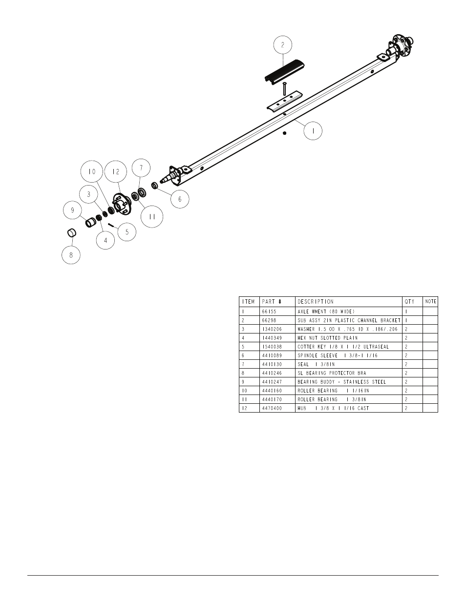
AXLE
Place one of the spring bracket bushings into the rear of the spring
bracket and secure with a 9/16” x 3-1/4” hex bolt and hex lock nut.
Repeat in other spring bracket.
Position the axle under the frame, then hook the hook loop of the
spring around the bushings just installed. Note that if the axle is
positioned too low when trying to hook, the hooks will not hook
around the bushings.
Once tightened, rotate the jack through its normal pivoting range to
make sure it is free to travel and is not binding up.
If jack pivots, place it on the tongue and secure in place with the
bolts and hardware provided with the trailer. Complete the assem-
bly of the winch head to the winch base. Assembly is complete.
WINCH POST INSTALLATION
The height that the bow eye is placed in your boat will determine
the length winch post required. Once this is determined, attach the
winch base to the tongue with three 1/2” x 4” carriage bolts and
lock nuts.
Align the holes in the
Profile 2000 mounting channel with the
holes in the top of the winch base. Attach the front of the winch
head mounting channel to the base by placing a 1/2” x 4” hex bolt
through the hole closest to the front of the winch base. Secure with
a lock nut. Do not tighten.
Note that the winch head can now be rotated either up or down.
Identify the correct hole combination to use to position the bow eye
roller just above the bow eye of your boat. When determined, se-
cure in this position by placing the bushing as shown in
Diagram C
inside the winch base so it aligns with the hole just identified for the
proper adjustment. Insert another 1/2” x 4-1/2” hex bolt through the
determined mounting hole in the mounting channel and winch base
making sure the bolt passes through the bushing as well. Secure
with a 1/2” lock nut. Tighten all bolts.
SPRINGS
Position the axle so it is properly aligned with the trailer and the
calipers are on the back side of the axle as shown.
Place the springs on the topside of the spring pads welded to the
axle.
(See Diagram D). Note that the hook end of the spring must
be mounted to the rear of the trailer. Place a spring clamp on the