ShoreLand'r BK1000U V.2 User Manual
Page 4
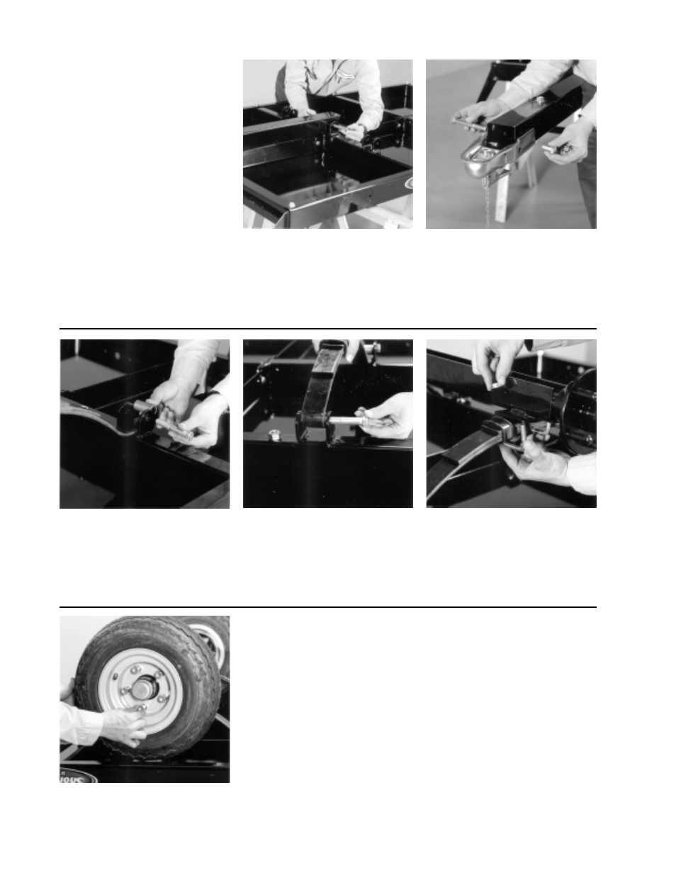
Slide the tongue into the front cross
weldment and secure with 1/2” X 5” hitch
pin w/lynch (Ref.# ). In the rear of the
tongue insert a 1/2” X 4-1/2” hex bolt
and two (2) 1/2” nylon washers (between
tongue and mounting plates). Secure
with a 1/2” flange lock nuts.
Mount the coupler to the tongue in the
two (2) top holes of the tongue using
one (1) 1/2” X 4” hex bolt in the rear hole.
Secure with a 1/2” flange lock nut.
Secure the front of the coupler to the
tongue using two (2) 1/2” X 1” hex bolts.
Secure with 1/2” flange lock nuts.
In the rear chassis cross weldments
insert the spring bushing spacer (Ref.#).
Secure the bushing to the chassis cross
weldments using 1/2” X 3-1/4” hex bolts
and 1/2” flange lock nuts.
Slide the spring into the rear chassis
cross weldment under the spring
bushing just installed. Insert the eye of
the spring in the front chassis cross
weldment and secure with the two (2)
remaining 9/16” X 3-1/4” hex bolts.
Tighten with 9/16” hex nuts.
Moun t the axle assembly to the springs
just installed using the 3/8” X 2-3/16” X
1-3/4” SUB (Ref.# ) and secure with
3/8” flange lock nuts.
Mount the tires to the axle assembly
using 1/2” lug nuts. Tighten to secure.
Use saw horses to aid in the assembly.
Lay the deck ( with the deck side down)
on the saw horses.
NOTE: The decals should face the
outside of the ATV strailer. Decals
closest to the front will determine the
front of the trailer.
Using a hoist or lifting device, lift your
ATV trailer off the saw horses and place
on it’s tires.
If installing the light kit, install when
trailer is upside down on the saw horses.
Double check all fasteners and tighten
before towing.
The ATV trailer is not highway or street
legal without the light kit being installed.
The light kit must be installed before
towing on public highways and/or
streets!
Midwest Industries, Inc.
Ida Grove, IA 51445
(800)859-3028
www.shorelandr.com
M305235
Page 4