ShoreLand'r TA0131 User Manual
Page 2
Midwest Industries, Inc.
Ida Grove, IA 51445
800.859.3028
www.shorelandr.com
0003801
Page 2
05/03/07
Trailer Lights
• Reconnect the wires for the trailer lights.
Match colors: red wire of the tongue har-
ness to yellow wire, green wire of tongue
harness to brown wire, and brown wire
of tongue harness to green wire of trailer
light harness. The connections must be
positive and completely connected.
• Reconnect the front side marker light
leads. Reconnect the white ground wire.
Note the white ground wire will now be
used for the grounding of the trailer lights
only. Once connected, the BrakeRite ac-
tuator will have its own positive ground.
• Pull the breakaway switch forward in the
tongue back to its original position and re-
attach using the screw removed earlier.
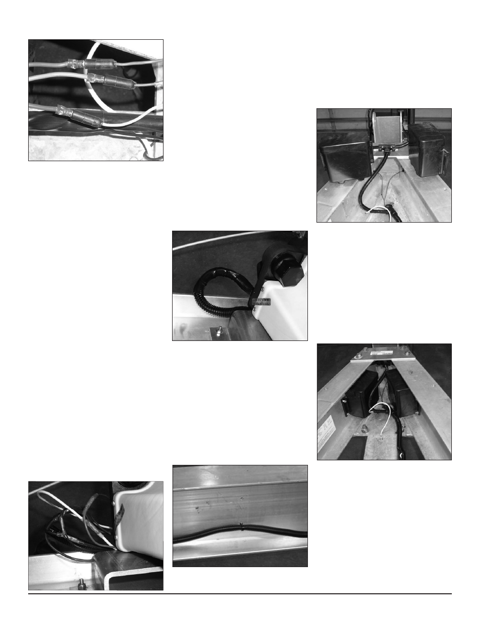
Connecting the Breakaway Actuator
• Slide the new wire harness section into
the tongue hole until the tee in the plastic
loom is at the tongue.
• Route the plastic loom down the side
frame of the trailer and over to the Brak-
eRite actuator. Route the plastic loom
behind the back side of the BrakeRite
actuator. The plastic loom will come out
on the rear side of the actuator for easier
connecting. Lay the plastic loom on the
bottom flange of the I-beam side frame.
• Slip another of the ¾” shrink tubes over
the end of the plastic loom until it is com-
pletely on the loom.
• Route the wires in the plastic loom over to
mate the wires from the BrakeRite actua-
tor. Note that the wires in the plastic loom
are staggered and positioned so they will
fit inside the shrink tube once the connec-
tions are complete.
• Mate the colored wires as follows:
Wires from plastic loom Wires from actuator
Black 12 gauge
Black 12 gauge
White 12 gauge
White 12 gauge
Blue 16 gauge
Blue 16 gauge
Violet 12 gauge
Violet 14 gauge
Black 16 gauge
Brown 16 guage
• Cut the wires from the BrakeRite actua-
tor to mate the connectors on the ends of
the mating wires inside the plastic loom.
Strip the wires back approximately 3/8”.
Insert the proper colored wires into the
proper crimp connectors and crimp.
• Heat the connections with a heat gun to
shrink the splice insulation around the
crimps.
• Slide the ¾” shrink tube over the connec-
tions just made so one end of the shrink
tube is over the wire restrainer on the ac-
tuator and the other end is over the plas-
tic loom. Shrink in position using a heat
gun.
• Route the wire loom down the bottom
flange of the trailer side frame. Identify a
spacing distance that will retain the wire
loom in the side frame of the trailer when
in use. Drill ¼” holes evenly spaced down
the side frame just above the wire loom.
• Insert a plastic wire tie into one of the
holes from the outside of the frame.
Note that the connector end will not slip
through the hole. Place the end of the
plastic wire tie around the plastic loom
then back through the hole. Insert the
end or the wire tie into the connector
end. Pull until the wire loom is secured to
the trailer side frame. Repeat this on the
remaining holes just drilled to secure the
complete harness in place.
• Connect the Break Away Batteries to
the new wire harness. (Note the battery
lead with the “Red” shrink tube is the pos-
itive lead and should be connected to the
positive side of the battery.)
Testing the System
• Check the system to make sure that prop-
er connections have been made when
installing the wire harness. This can be
checked by pulling the break away switch.
When pulled, the system should function
and the brakes should activate.
• Once the system checks out, re-install
the Break Away Batteries and the cases
to the side frames. Tighten.
• Plug the seven pin plug into a test rig and
cycle the system to assure there is a sat-
isfactory installation and the brakes are
being activated.
Installation is complete.
Reassemble the winch post to the settings
marked earlier when it was removed. Place
the boat back on the trailer.