ShoreLand'r SL30BAL User Manual
Page 3
Midwest Industries, Inc.
Ida Grove, IA 51445
800.859.3028
www.shorelandr.com
0003627
Page 3
3/08/06
Tongue
The tongue comes shipped positioned backwards in the
frame. Remove the nut and bolt that holds the tongue in place
and discard. Slide the tongue out from it’s shipping position
and re-install in the front tongue channel. Line the holes in the
tongue with the holes in the tongue channel. Secure with a 1/2”
x 4” hex bolt and 1/2” lock nut in the front cross hole.
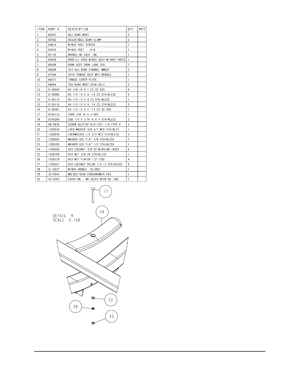
Remove the wire harness from the rear of the tongue. Place
the wire harness and the brake line through the hole in the
tongue cover plate. (See Detail G). Secure the tongue cover
plate in position with a 1/2” x 1-1/2” hex bolt and 1/2” lock nut.
Tighten. Plug the tongue wire harness ends into the frame
harnesses by matching colors and ends. Push the extra
wire into the rear of the tongue or remove the grommets in
the side frame and place the extra wire in the side frame.
Replace grommets just removed.
White Ground Wire Installation
Place the self-tapping screw provided through the round
metal ring on the white ground wire of the tongue harness
located at the rear of the tongue. Attach the ground wire
to the main frame by driving the screw in the hole pro-
vided next to the tongue channel of the frame. This will as-
sure a positive ground for the lighting.
Safety Chains
Place 1/2” x 5” hex bolt through a 1/2” flat washer and the last
link of the safety chains. Insert in the hole (bottom front of the
actuator) on the tongue. Place the second chain on the same
bolt that is extending through the other side of the tongue.
Secure with a 1/2” flat washer and hex lock nut.
Brake Line
Locate the brass brake line coupling. Remove the plastic cap
and thread the brake line coming out the rear of the tongue
into one end of the coupling. Bend the line in a smooth gradual
radius being careful not to kink the line. Bend so it can be
mated to the brake line from the side frame. Once aligned,
thread the side frame brake line into the other end of
the coupling. Tighten both lines into the coupling.
Winch Post Assembly
(See Detail J, Page 2). The height that the bow eye is located
on your boat will determine the winch post length required.
Once this is determined, attach the winch base to the tongue
with three 1/2” x 4-1/2” hex bolts and lock nuts.
Align the holes in the Profile 2000 mounting channel with
the holes in the top of the winch base. Attach the front of
the winch head mounting channel to the base with a 1/2” x
4-1/2” hex bolt through the hole closest to the front of the
winch base. Secure with a lock nut. Do not tighten.
The winch head can be rotated either up or down. Identify
the correct hole combination to position the bow eye roller
just above the bow eye of your boat. Secure in position by
placing the bushing as shown in Detail J, Ref #1, inside
the winch base so it aligns with the hole just identified for
the proper adjustment. Insert another 1/2” x 4-1/2” hex bolt
through the determined mounting hole in the mounting
channel and winch base making sure the bolt passes
through the bushing.
Secure with a 1/2” lock nut. Tighten all bolts.
IMPORTANT: All hardware for your trailer is stainless
steel. It is important that you use an anti-seize material
on the bolt threads when assembling to prevent gauld-
ing.