Frame assembly instructions – ShoreLand'r SL150T User Manual
Page 2
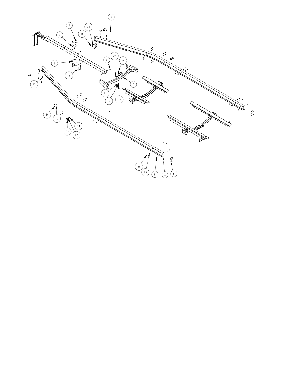
REF# PART# DESCRIPTION
QTY
1
6623800 TONGUE PLATE ....................................... 1
2
6623900 TONGUE PLATE TOP ............................... 1
3
6624500 TONGUE CROSS WMENT ....................... 1
4
66258
SIDEFRAME - ALUMINUM TRIAXLE ....... 2
5
66518
ALUM TRAILER END CAP WMENT ......... 2
6
0150279 HH 1/4-20 X 1 CS SS GR5 ........................ 4
7
0150281 HH 1/2-13 X 1-1/2 CS SS GR5.................. 16
8
0150286 HH 5/8-11 X 7 CS SS GR5 ........................ 1
9
0150287 HH 5/8-11 X 1-1/2 CS SS GR5.................. 10
10
0250131 CARR 3/8-16 X 5 SS GR5 ......................... 1
11
0340201 SUB 5/8 X 5 3/4 X 6 1/2 ............................. 2
12
0810971 SCREW SELFTAPPING TYPE A #6X1/2 . 8
13
1350030 LOCKWASHER 3/8 STAINLESS .............. 1
14
1350095 WASHER USS FLAT 3/8 STAINLESS ...... 1
15
1350100 WASHER USS FLAT 1/2 STAINLESS ...... 24
16
1350105 WASHER USS FLAT 5/8 STAINLESS ...... 11
17
1350197 BEVELED WASHER (ALUMINUM) ........... 8
18
1450109 HEX NUT 3/8-16 STAINLESS ................... 1
19
1450356 HEX LOCKNUT NYLON 1/4-20 SS ........... 4
20
1450357 HEX LOCKNUT NYLON 1/2-13 SS ........... 16
21
1450359 HEX LOCKNUT NYLON 5/8-11 SS ........... 15
22
3510542 MOLDED REAR CROSSMEMBER PAD .. 1
23
5110112 MARINE YELLOW CLEARANCE LIGHT .. 4
24
5110369 LIGHT BEZEL SELF GROUND SCREW .. 4
25
5110501 AUSCO TRAILER BATTERY BOX ............ 1
Frame Assembly Instructions
Frame Material List
Frame:
Your SL95T side frames and crossmembers is assembled at the
manufacturer. The spring brackets and fenders are also moun ted
by the manufacturer.
Battery Box:
Mount the battery box to the right front side frame near the tongue
cap of the SL95T. The battery box will sit flush against the side
frame between the flanges of the side frame i-beam, match the
hole pattern. Secure the battery box to the side frame using four
(4) 1/4 X 1 stainless steel hex head bolts and four (4) 1/4
stainless steel hex lock nuts with nylon inserts.
Frame Assembly Instructions
Actuator:
Mount the brake actuator to the right spring bracket in the hole
pattern designated for the actuator unit. Secure the actuator to the
spring bracket using four (4) 1/4 X 1 stainless steel hex head
bolts and four (4) 1/4 stainless steel hex lock nuts with nylon
inserts. Connect the blue wires.
Wiring:
Run the tongue wire harness through the tongue tube to the rear
and connect to the side frame wire harnesses located at
tehtongue cap on teh first crossmember. With a hooked wire -
hook the tongue wire harenss and pull wires through the wire only
tongue plate - approximately 30 back on the tongue tube. The
black, brown and white (ground) wires are needed. Push the
remainder of the wires back into the tongue tube. The brown wires
will run to the amber side marker light and plug in. The black wires
will run to the battery box. NOTE: Refer to the wiring instructions
that are available with battery for the connecting procedures. The
white ground wire must be grounded to the trailer frame with a 3/
4 self grounding tap screw. Install grommets inall wire holes.
Refer to page 7 for the vehicle and tongue wire harness connec-
tions diagram.
Tongue:
Slide the tongue into the tongue frame cap at the front of the
trailer back into the tongue channel weldment on the front
crossmember. Secure with a 5/8 X 7 stainless steel hex bolt, 5/8
stainless steel flat washer and 5/8 stainless steel hex lock nut
with nylon insert. Secure the tongue inside the tongue cap on the
frame using two (2) 5/8 X 5-3/4 X 6-1/2 square u-bolts and four
(4) 5/8 stainless steel hex lock nut with nylon inserts.
Jack:
NOTE: Remove the hardware provided by the jack manufacturer
and discard. Using the mounting plates provided by the jack
manufacuter, mount the jack on the tongue in a location that best
fits your watercraft. Secure with four (4) 3/8 X 6 stainless steel
hex bolts and four (4) 3/8 stainless steel lock nuts with nylon
inserts located in the hardware bag (66270) within the frame
bundle.